
Pushing device for machining hardware mechanical part

A technology of mechanical parts and pushing devices, which is applied to conveyor objects, transportation and packaging, etc., can solve the problems of single pushing position, low pushing universality, increase equipment cost, etc., and achieve diverse and universal pushing positions. High and cost saving effect

Inactive Publication Date: 2019-07-19
浙江捷力五金机械科技股份有限公司
View PDF0 Cites 4 Cited by
  • Summary
  • Abstract
  • Description
  • Claims
  • Application Information

AI Technical Summary

Problems solved by technology

[0005] The object of the present invention is to provide a kind of pushing device for processing hardware mechanical parts, to solve the problem that the existing pushing device proposed in the above background technology has low versatility in pushing materials, and the pushing position is single. When it is necessary to push materials in different positions , it is necessary to set up multiple groups, which is not only time-consuming and labor-intensive, but also increases the cost of equipment

Method used


Image

  • Pushing device for machining hardware mechanical part
  • Pushing device for machining hardware mechanical part
  • Pushing device for machining hardware mechanical part

Examples


Embodiment Construction

[0027] The following will clearly and completely describe the technical solutions in the embodiments of the present invention with reference to the accompanying drawings in the embodiments of the present invention. Obviously, the described embodiments are only some, not all, embodiments of the present invention. Based on the embodiments of the present invention, all other embodiments obtained by persons of ordinary skill in the art without making creative efforts belong to the protection scope of the present invention.

[0028] In describing the present invention, it should be understood that the terms "center", "longitudinal", "transverse", "length", "width", "thickness", "upper", "lower", "front", " Back", "Left", "Right", "Vertical", "Horizontal", "Top", "Bottom", "Inner", "Outer", "Clockwise", "Counterclockwise", "Axial", The orientation or positional relationship indicated by "radial", "circumferential", etc. is based on the orientation or positional relationship shown in...


PUM


Abstract

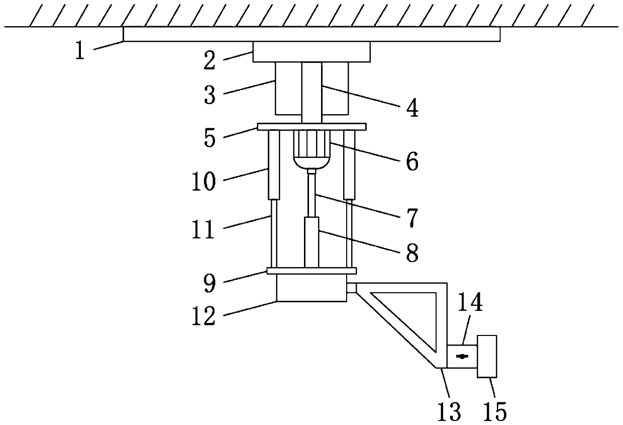
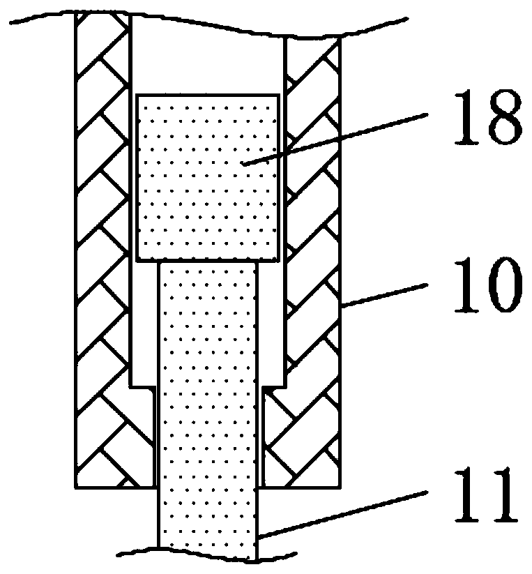
The invention discloses a pushing device for machining a hardware mechanical part, and relates to the field of hardware mechanical part machining equipment. The pushing device for machining the hardware mechanical part comprises an installation top plate, wherein a sliding rail is fixedly connected to the middle of the front side of the lower surface of the installation top plate; a first electricpushing rod is fixedly connected to the middle of the rear side of the lower surface of the installation top plate; a connecting column is arranged on the lower surface of the sliding rail; the bottom end of the connecting column is fixedly connected with a first fixing plate; a servo motor is fixedly connected to the middle of the lower surface of the first fixing plate; a lead screw is fixedlyconnected to the middle of the lower surface of the servo motor through a rotating shaft; a threaded sleeve is arranged at the bottom end of the lead screw; a second fixing plate is fixedly connectedto the bottom end of the threaded sleeve; and a second electric pushing rod is fixedly connected to the lower surface of the second fixing plate. According to the pushing device for machining the hardware mechanical part, the transverse pushing position can be adjusted, materials at different positions can be pushed, the pushing positions are various, the universality is high, a plurality of groups are avoided, and the investment cost of equipment is saved.

Description

technical field [0001] The invention relates to the field of processing equipment for hardware mechanical parts, in particular to a material pushing device for processing hardware mechanical parts. Background technique [0002] Hardware refers to five metals including gold, silver, copper, iron and tin. After manual processing, it can be made into works of art or metal devices such as knives and swords. Hardware in modern society is more extensive, such as hardware tools, hardware parts, daily hardware, construction hardware and security supplies. Most hardware products are not final consumer goods. [0003] During the feeding process of hardware and mechanical parts, material blockages are prone to occur. The traditional pushing device has low versatility for pushing materials and a single pushing position. Equipment costs are also increased. [0004] Therefore, it is necessary to invent a metal machine parts processing pushing device to solve the above problems. Cont...

Claims


Application Information

Patent Timeline
IPC IPC(8): B65G47/82
CPCB65G47/82
Inventor 肖春生肖春林赖龙伟
Owner 浙江捷力五金机械科技股份有限公司
Learn More