Temperature strain monitoring system for fluid heating snow melting pavement

A monitoring system and temperature strain technology, applied in the application of thermometers, electrical/magnetic solid deformation measurement, thermometers, etc., can solve the problems of road surface safety, only focus on the effect of snow melting, etc., and achieve the effect of ensuring safe operation.

Inactive Publication Date: 2019-07-19
HARBIN INST OF TECH
View PDF6 Cites 0 Cited by
  • Summary
  • Abstract
  • Description
  • Claims
  • Application Information

AI Technical Summary

Problems solved by technology

[0005] In order to solve the traditional fluid-heated snow-melting road surface, which only pays attention to the snow-melting effect, but ignores the temperature strain caused by the impact of heat flow, and then causes the safety problem of the road surface, it further provides a fluid-heated snow-melting road surface temperature and strain monitoring system

Method used


Image

  • Temperature strain monitoring system for fluid heating snow melting pavement
  • Temperature strain monitoring system for fluid heating snow melting pavement
  • Temperature strain monitoring system for fluid heating snow melting pavement

Examples


specific Embodiment approach 1

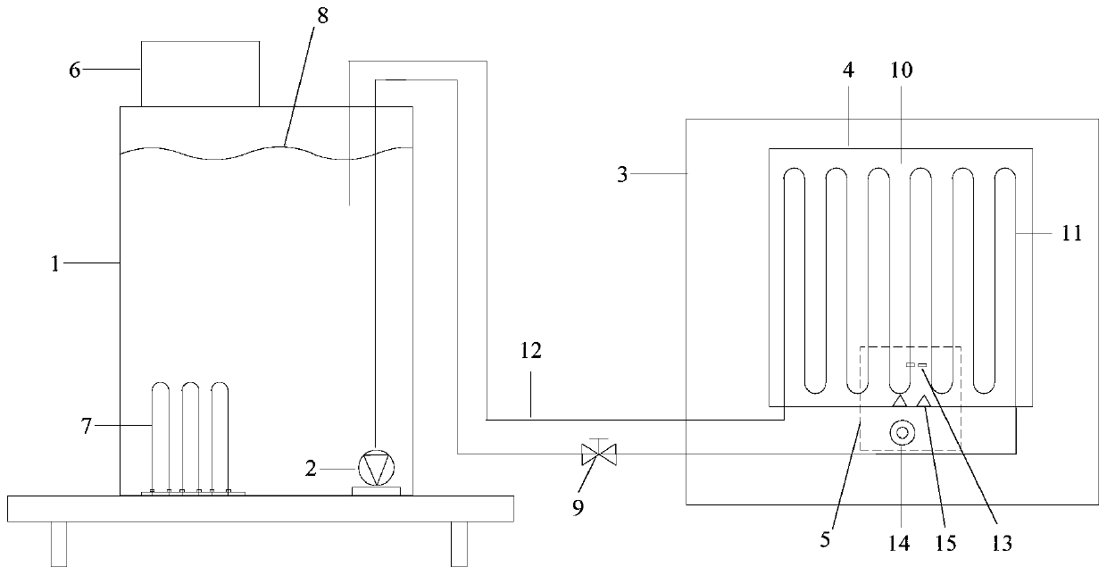
[0031] Specific implementation mode one: combine Figure 1 to Figure 7 Describe this embodiment mode, a kind of fluid heating snow-melting road surface temperature strain monitoring system of this embodiment mode, it comprises heating system, circulating pump 2, environment box 3, road surface system 4, monitoring system 5, control valve 9 and two connection tube 12,

[0032] The heating system includes a heating water tank 1, a power distribution box 6 and an electric heating tube 7. The electric heating tube 7 is fixed on the inner bottom surface of the heating water tank 1, and the distribution box 6 is installed on the outer upper end surface of the heating water tank 1. The power distribution box 6 passes through the wire Connected with the electric heating tube 7, the distribution box 6 is used to control the opening and closing of the electric heating tube 7, and the power adjustment of the electric heating tube 7, and the upper side wall of the heating water tank 1 is ...

specific Embodiment approach 2

[0048] Specific implementation mode two: combination Figure 5 Describe this embodiment, the cement concrete pavement 10 internal pipeline 11 center line of the present embodiment is provided with a plurality of temperature sensors 13 along the vertical direction from top to bottom sequentially, the cement concrete pavement 10 internal adjacent pipeline 11 center line A plurality of temperature sensors 13 are arranged in sequence from top to bottom in the vertical direction, and the distance between all the temperature sensors 13 and the side surface of the cement concrete pavement 10 is 5 cm. So set, the temperature sensor 13 is used to monitor and record the temperature at different depths of the road surface. Other compositions and connections are the same as in the first embodiment.

[0049] The temperature sensor 13 of this embodiment is used to monitor and record the temperature at different depths of the road surface, the temperature measurement range is -50°C to +120°...

specific Embodiment approach 3

[0050] Specific implementation mode three: combination Image 6 Describe this embodiment. The digital speckle meter acquisition device in this embodiment includes a bracket, a slide rail, a lighting lamp, a camera A and a camera B. The bracket is erected on one side of the cement concrete pavement 10, and the slide rail is horizontally arranged on the bracket The lighting lamp is installed in the middle of the slide rail. Camera A and camera B are located on both sides of the lighting lamp. Both camera A and camera B are slidingly connected with the slide rail. The lens of camera A and the lens of camera B Both the lens and the lighting lamp are directed towards the end surface to be measured of the cement concrete pavement 10 , and the signal output terminals of the camera A and the camera B are connected with the signal input terminal of the digital speckle meter 14 . Other compositions and connections are the same as those in Embodiment 1 or Embodiment 2.

[0051] The digi...


PUM


Abstract

The invention discloses a temperature strain monitoring system for a fluid heating snow melting pavement, and relates to the field of temperature strain monitoring of the fluid heating snow melting pavement. The invention solves the problem of pavement safety caused by the fact that traditional fluid heating snow melting pavement only pays attention to the snow melting effect and neglects the temperature strain generated by the heat flow impact action. The temperature strain monitoring system for a fluid heating snow melting pavement comprises a heating system, a circulating pump, an environment box, a pavement system and a monitoring system, wherein the heating system comprises a heating water tank, a distribution box and an electric heating pipe; the electric heating pipe is arranged inthe heating water tank; the pavement system is arranged in the environment box; the pavement system comprises a cement concrete pavement and a pipeline; the pipeline is horizontally embedded in the cement concrete pavement and is connected with the heating water tank through a connecting pipe; the connecting pipe is provided with the circulating pump and a control valve; a temperature sensor and aresistance strain gauge are arranged inside the cement concrete pavement; and a digital speckle instrument acquisition device is erected on one side of the cement concrete pavement. The invention isused for testing the temperature strain of the airport snow melting road surface.

Description

technical field [0001] The invention relates to the field of monitoring the temperature and strain of a fluid-heated snow-melting road surface, in particular to a temperature-strain monitoring system for a fluid-heated snow-melting road surface. Background technique [0002] Snow and ice removal from road surfaces has become a typical safety issue in airport operations. The traditional deicing methods for runways mainly use snow removal machinery and deicing salt. However, these two methods have low deicing efficiency when the temperature is low and the snowfall is large, and they have negative effects on the surface structure and the environment. [0003] At present, the circulating fluid heating system has become an effective alternative method for deicing and snowing the airport pavement. Its working principle is: use the circulating fluid to transfer the heat of the underground soil to the pipeline inside the pavement, and then transfer the heat to the surface through t...

Claims


Application Information

Patent Timeline
Patent Type & Authority Applications(China)
IPC IPC(8): G01K13/00G01B11/16G01B7/16
CPCG01K13/00G01B7/18G01B11/16
Inventor 谭忆秋张驰徐慧宁付忠斌
Owner HARBIN INST OF TECH
Why Eureka
Try Eureka