Scanning detection method for environmental gases and laser radar
An environmental gas and detection method technology, applied in the field of laser remote sensing, can solve the problems of high temporal and spatial resolution, long detection distance, and insufficient quantification of atmospheric pollutant emissions, so as to avoid detection errors, reduce requirements, and improve scanning detection accuracy Effect
- Summary
- Abstract
- Description
- Claims
- Application Information
AI Technical Summary
Problems solved by technology
Method used
Image

Examples
Embodiment Construction
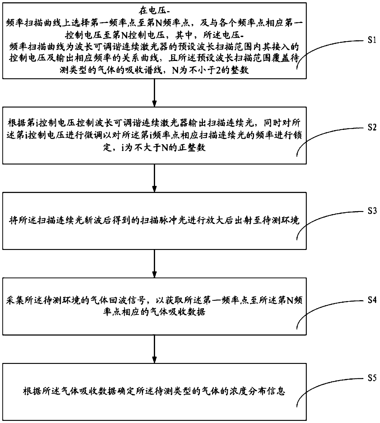
[0056] The following will clearly and completely describe the technical solutions in the embodiments of the present invention with reference to the accompanying drawings in the embodiments of the present invention. Obviously, the described embodiments are only some, not all, embodiments of the present invention. Based on the embodiments of the present invention, all other embodiments obtained by persons of ordinary skill in the art without making creative efforts belong to the protection scope of the present invention.
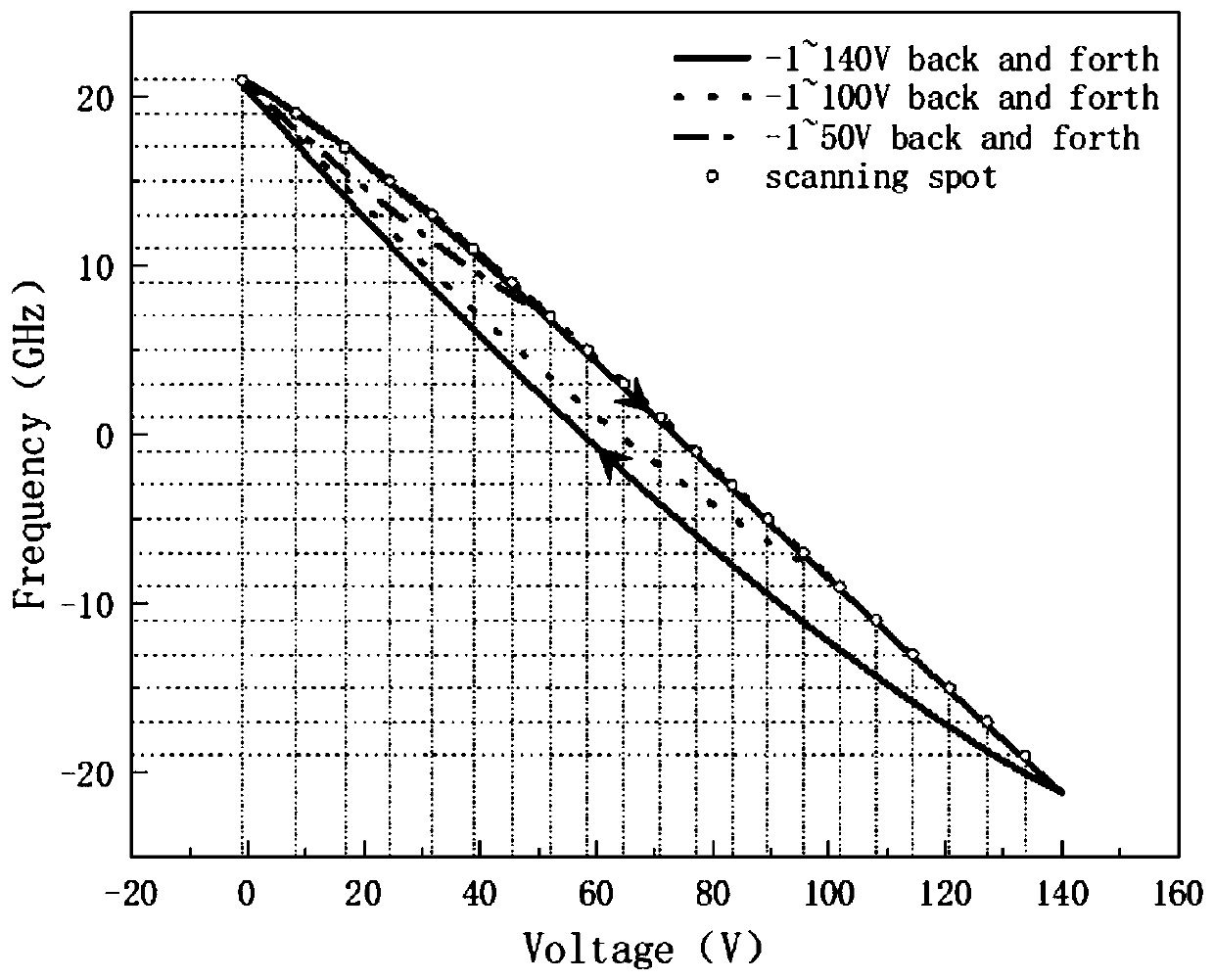
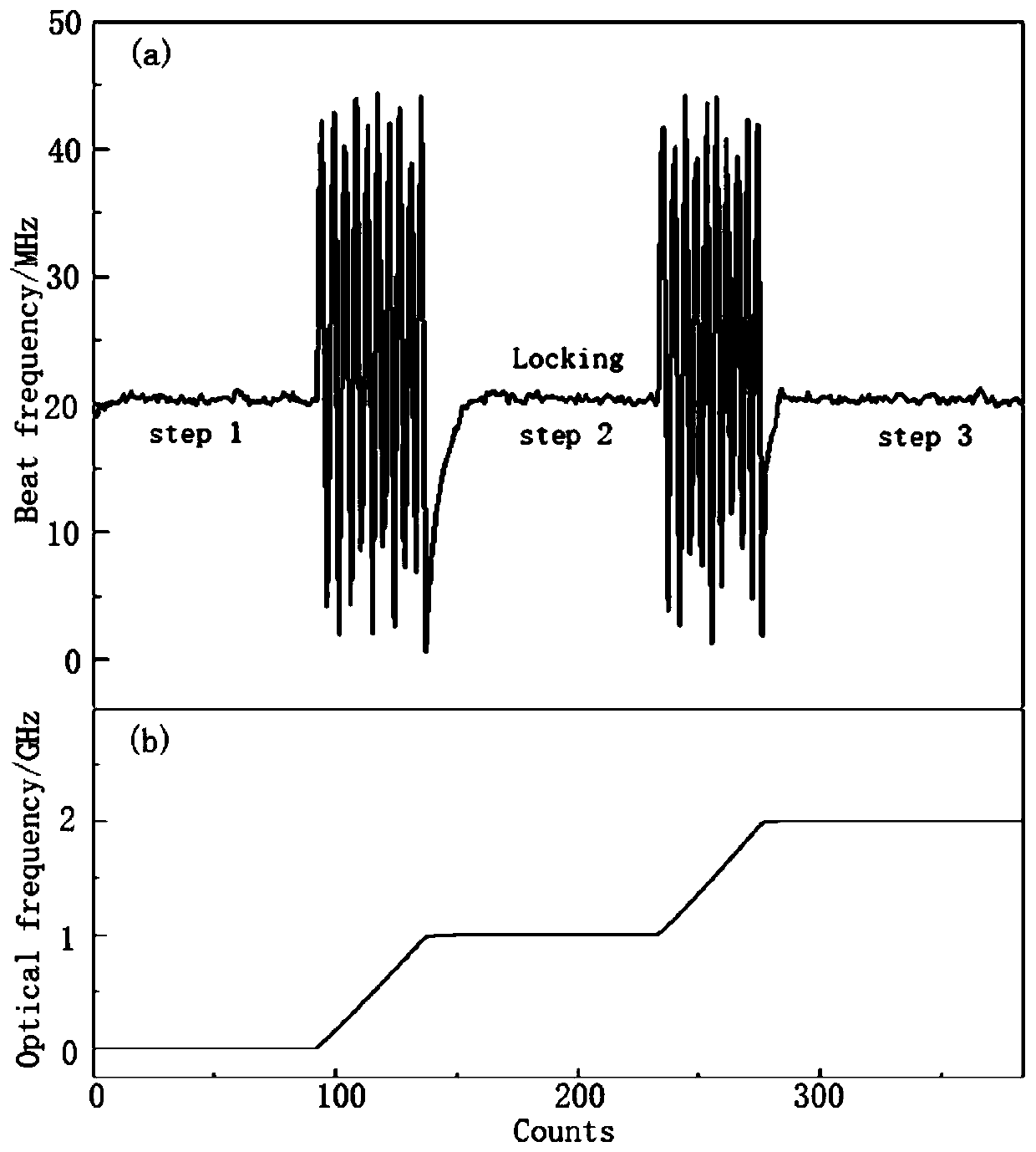
[0057] As mentioned in the background technology, lidar detection can be divided into many methods, among which differential absorption lidar has realized the detection of various gas components in the atmosphere, and differential absorption lidar usually uses two wavelengths of laser light, one of which is in the The absorption cross-section on the gas to be measured is strong, and the absorption cross-section of the laser of another wavelength on the gas to b...
PUM
 Abstract
Description
Claims
Application Information
PatSnap Eureka turns technology decisions into work you can execute. Powered by our Innovation Knowledge Graph, it runs expert workflows across engineering, life sciences, materials and intellectual property. Get your review-ready output in minutes.


