
Medical constant-pressure ankle pump device

A medical ankle pump technology, applied in the field of medical constant pressure ankle pump devices, can solve the problems of uncontrollable massage force and cumbersome operation, and achieve the effect of increasing the scope of application, simple operation, and reducing investment

Active Publication Date: 2019-07-23
QINGDAO MUNICIPAL HOSPITAL
View PDF5 Cites 7 Cited by
  • Summary
  • Abstract
  • Description
  • Claims
  • Application Information

AI Technical Summary

Problems solved by technology

[0005] The purpose of the present invention is to provide a medical constant pressure ankle pump device with simple operation, good rehabilitation effect and uniform massage force for the problems of cumbersome operation of the existing ankle pump process and uncontrollable massage force

Method used


Image

  • Medical constant-pressure ankle pump device
  • Medical constant-pressure ankle pump device
  • Medical constant-pressure ankle pump device

Examples


Embodiment 1

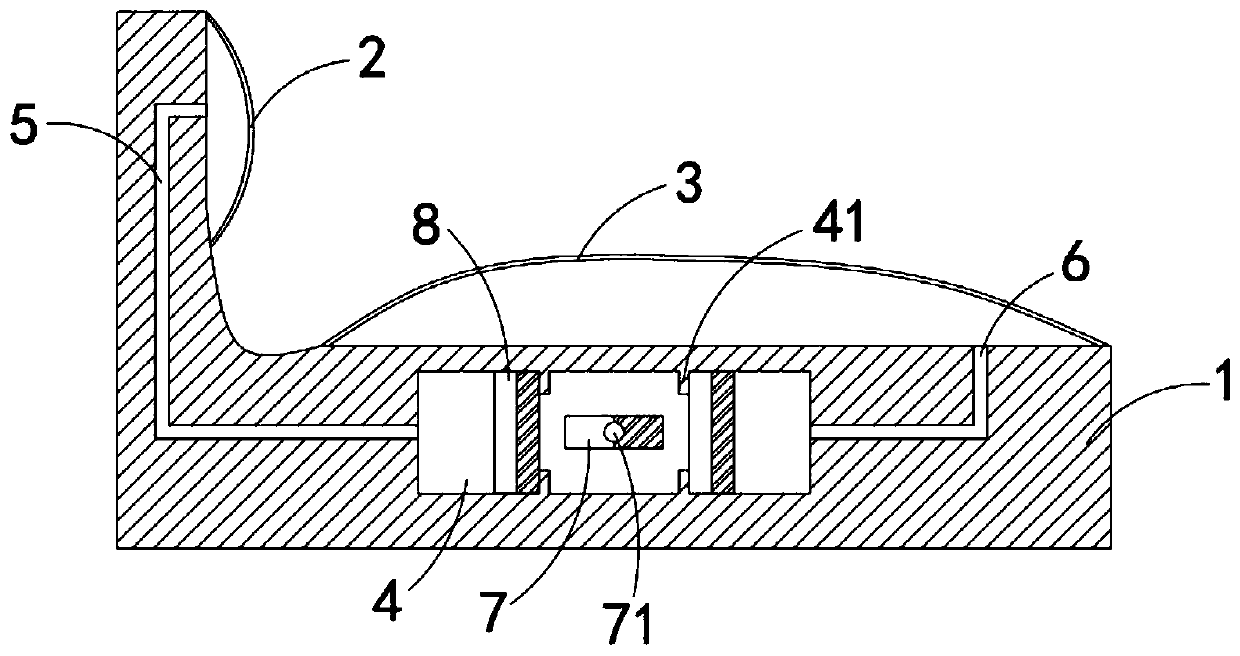
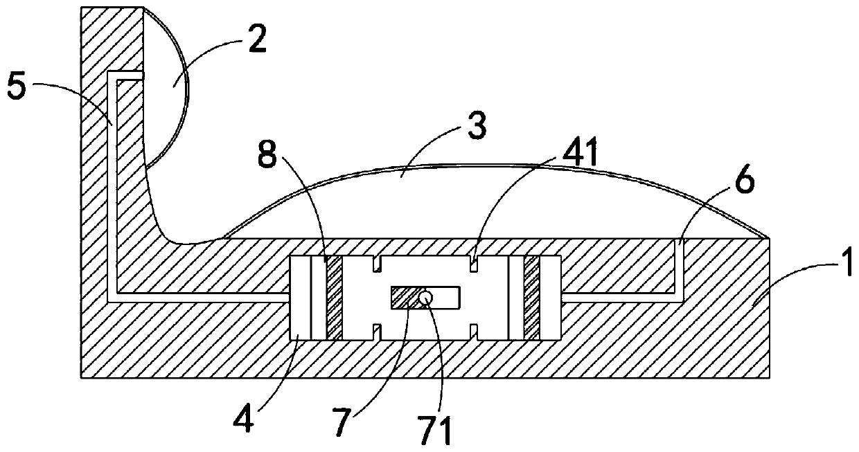
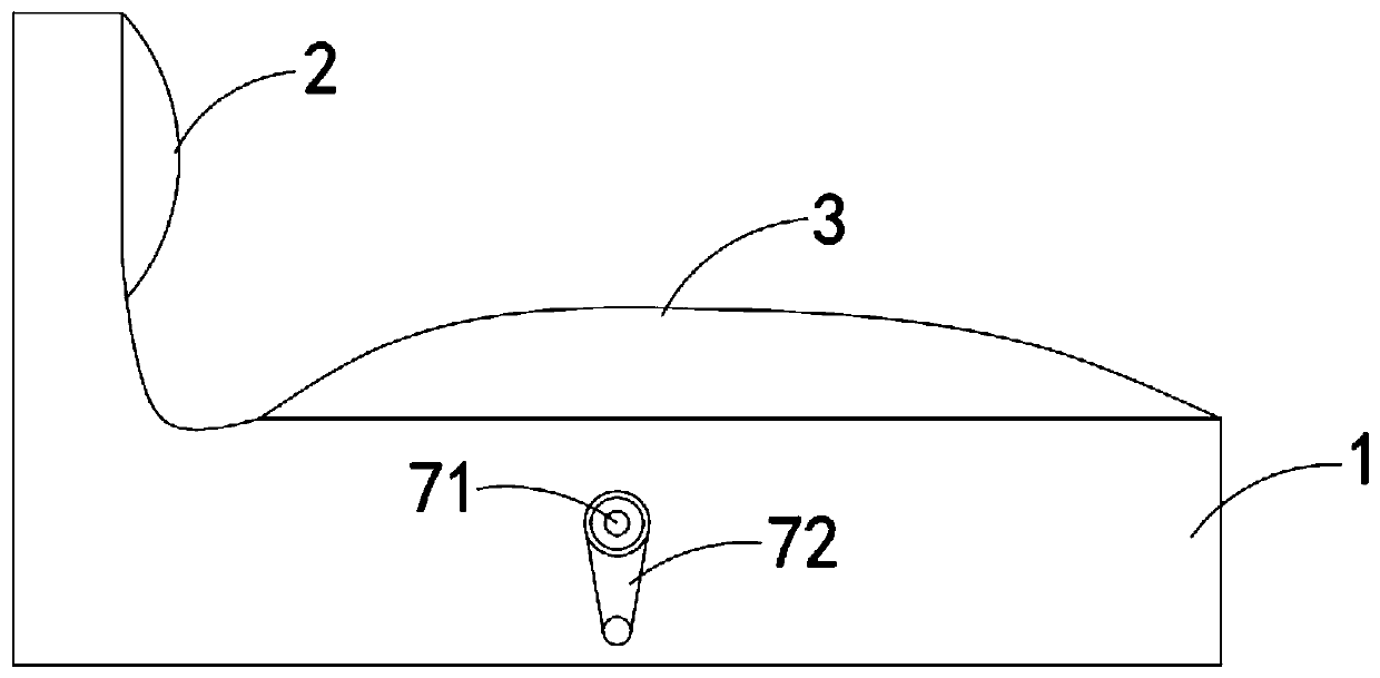
[0021] Such as Figure 1-3 As shown, a medical constant pressure ankle pump device includes a base 1, the base 1 is L-shaped, a massage airbag 2 is fixedly connected to the side wall of the vertical section of the base 1, and a massage airbag 2 is fixedly connected to the side wall of the horizontal section of the base 1. Squeeze airbag 3, massage airbag 2 and squeeze airbag 3 are all made of elastic material such as rubber, wherein massage airbag 2 corresponds to the position of the sole of the foot, pressing airbag 3 corresponds to the position of the calf, and the horizontal section of the L-shaped base 1 and the vertical section The junction is recessed downward to form a groove for receiving the heel, allowing the entire device to fit the anatomy of the patient's lower leg and foot.

[0022] The base 1 is provided with a bar-shaped cavity 4, and the bar-shaped cavity 4 communicates with the massage air bag 2 and the extruding air bag 3 respectively through the first air d...

Embodiment 2

[0026] Such as Figure 4 As shown, the difference between this embodiment and Embodiment 1 is that: the side wall of the strip-shaped cavity 4 is fixedly connected with a multi-turn closed coil 91, and the winding direction of the closed coil 91 is perpendicular to the rotation direction of the permanent magnet post 7 , when the permanent magnetic column 7 is rotating, the magnetic induction line of the permanent magnetic column 7 can cut the closed coil 91 and move, so that an induced current is generated in the closed coil 91, and an electric heating plate 92 is arranged in the extrusion air bag 3, and the electric heating plate 92 is fixedly installed On the upper end of the base 1 , the electric heating plate 92 is coupled and connected in the loop formed by the closed coil 91 .

[0027] In this embodiment, when the permanent magnet column 7 continues to rotate, the magnetic induction line of the permanent magnet column 7 can move to cut the closed coil 91, so that an indu...


PUM


Abstract

The present invention belongs to the field of medical technology equipment and particularly relates to a medical constant-pressure ankle pump device. The medical constant-pressure ankle pump device comprises a base seat, the base seat is L-shaped, a massage airbag is fixedly connected with a side wall of a vertical section of the base seat, a squeeze airbag is fixedly connected with a side wall ofa horizontal section of the base seat, the base seat is internally provided with a strip-shaped cavity, the strip-shaped cavity communicates respectively with the massage airbag and the squeeze airbag through a first air transporting pipe and a second air transporting pipe, the strip-shaped cavity is internally rotatably connected with a permanent magnet column, and both sides of the permanent magnet column are provided with magnetic piston blocks slidbly and sealedly connected with the strip-shaped cavity. By arranging the massage airbag and squeeze airbag, when the permanent magnet column continuously rotates, the medical constant-pressure ankle pump device can realize patient ankle pump and calf pressing effects at the same time, can save physical strength of physicians and is also relatively simple in operations. Besides, magnetic forces between the permanent magnet column and magnetic piston blocks are constant, so that the massage airbag and the squeeze airbag can be subjected to even force-applying every time, thereby realizing a better rehabilitation effect.

Description

technical field [0001] The invention belongs to the field of medical technology equipment, in particular to a medical constant pressure ankle pump device. Background technique [0002] Ankle pump exercise refers to the movement of the ankle joint, which acts like a pump to promote the blood pressure circulation and lymphatic circulation of the lower limbs. It includes the flexion and extension of the ankle joint and the ankle movement. Ankle pump exercise plays a vital role in the functional recovery of patients after long-term bed rest and surgery. [0003] Existing ankle pump exercises are generally done manually by doctors, and the strength of each massage cannot be controlled. In addition, depending on the doctor's proficiency and the strength of the doctor, it will also affect the patient's therapeutic effect; in addition, In order to improve the massage effect, in the process of massaging the patient, it is also necessary to apply hot compresses to the patient's legs ...

Claims


Application Information

Patent Timeline
IPC IPC(8): A61H1/02A61H9/00A61H39/04A61F7/00
CPCA61F7/0053A61F2007/0043A61F2007/0055A61H1/0266A61H9/0078A61H39/04A61H2201/0207A61H2201/164A61H2205/106A61H2205/12A61H2205/125
Inventor 杨西凤
Owner QINGDAO MUNICIPAL HOSPITAL
Features
  • Generate Ideas
  • Intellectual Property
  • Life Sciences
  • Materials
  • Tech Scout
  • Unparalleled Data Quality
  • Higher Quality Content
  • 60% Fewer Hallucinations
Learn More