Assembling method of device for clamping insulator
An assembly method and technology of insulators, applied in workpiece clamping devices, manufacturing tools, etc., can solve the problems of potential safety hazards, easy falling off and sliding, and inability to apply insulators, etc., and achieve the effect of improving safety and facilitating disassembly and assembly
- Summary
- Abstract
- Description
- Claims
- Application Information
AI Technical Summary
Problems solved by technology
Method used
Image
Examples
specific Embodiment approach 1
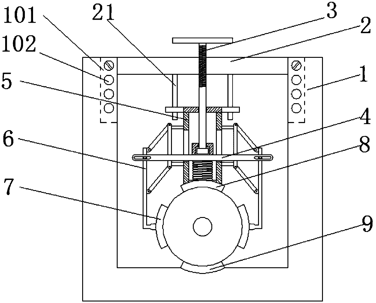
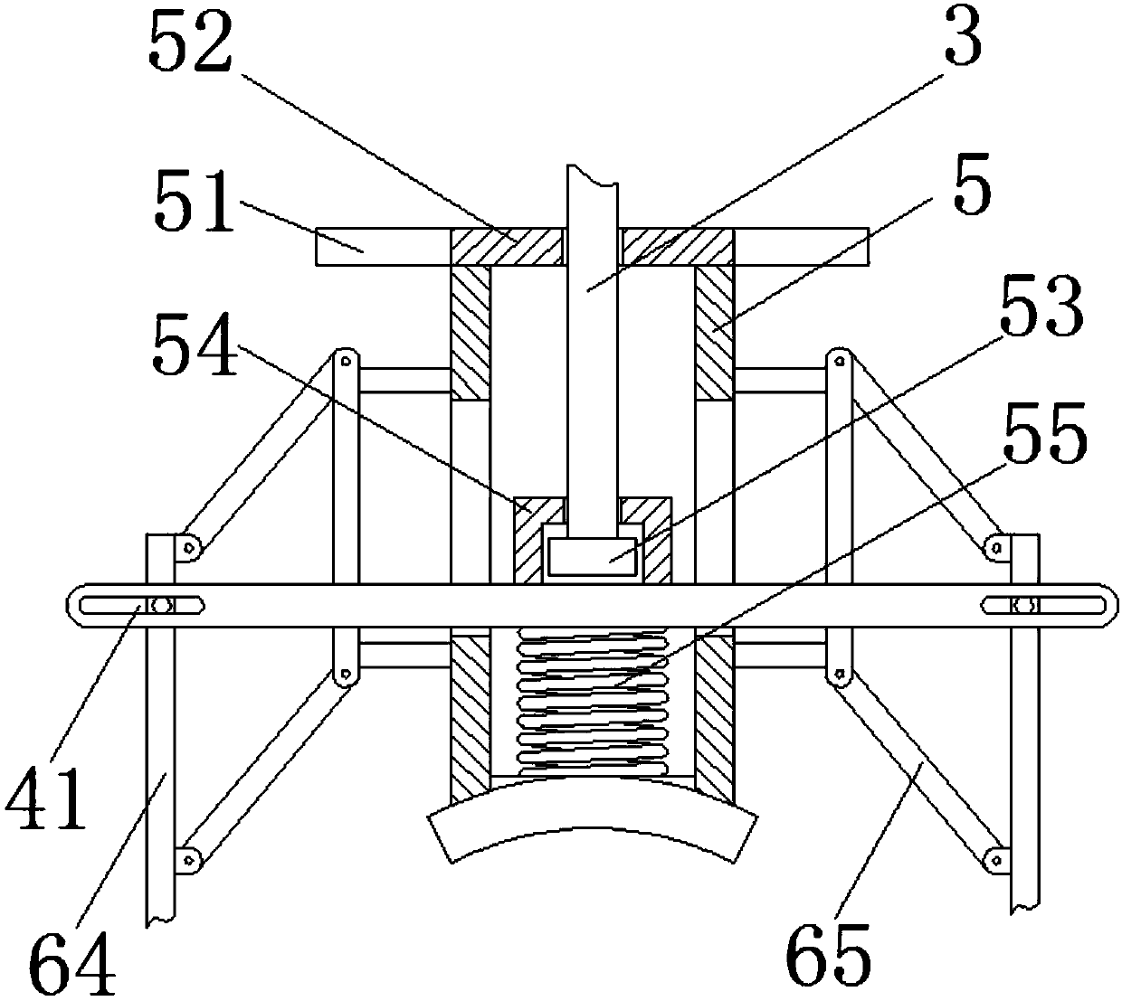
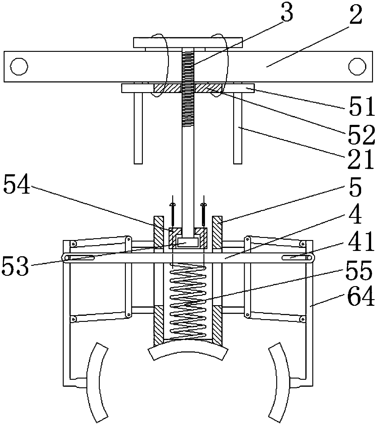
[0032] combine figure 1 and figure 2As shown, a device for clamping insulators disclosed in this embodiment includes: a U-shaped frame 1 and an open cross bar 2. The U-shaped frame 1 includes two vertical side arms, and the inner sides of the two side arms are A chute 101 in the vertical direction is provided, and several positioning holes 102 are arranged at intervals along the vertical direction on the side of the chute 101, which is convenient for adjusting the installation position of the opening cross bar 2. The two ends of the opening cross bar 2 are respectively Inserted into the chute on both sides of the U-shaped frame 1 and fixed by bolts, the lower end of the opening cross bar 2 is provided with two light rods 21 in parallel, the upper ends of the light rods 21 are fixedly connected with the opening cross bar 2, and the light The lower ends of the rods 21 are suspended in the air, and a sleeve slider 51 is arranged on the two light rods 21, and the two sleeve slid...
specific Embodiment approach 2
[0036] This embodiment is based on the specific implementation mode 1, further, in combination with Figure 4 As shown, the connection between the movable rod 64 of the quadrilateral link frame 6 and the side clamping block 7 is a hinged structure, the hinged position of the movable rod 64 is provided with a hinged positioning block 61, and the hinged positioning block 61 is arranged on the movable rod 64 The hinged surface of the side clamping block 7 is facing the side of the side clamping block 7, and the hinged position of the side clamping block 7 is provided with a hinge block slide groove 71 toward the side of the movable rod 64, and the hinge block slide groove 71 is arc-shaped, so The hinged positioning block 61 is arranged in the hinged block slide groove 71 , and a return spring is arranged between both ends of the hinged positioning block 61 and the inner wall of the hinged block slide groove 71 .
[0037] In the process of clamping the insulator by the device, for...
specific Embodiment approach 3
[0039] This embodiment is based on the specific implementation mode 1, further, in combination with Figure 5 As shown, the connection between the movable rod 64 of the quadrilateral link frame 6 and the side clamping block 7 is a hinged structure, and the hinged position of the movable rod 64 is provided with a hinged positioning groove 62, and the hinged positioning groove 62 is in the direction of the hinge axis. The small pit, the hinged position of the side clamping block 7 is provided with a hinged positioning ball 72, the hinged positioning ball 72 is arranged in the positioning ball chute 73, and the positioning ball chute 73 is fixedly connected with the side clamping block 7, A spring is arranged between the hinged positioning ball 72 and the positioning ball chute 73, and the outside of the hinged positioning groove 62 is provided with a reset inclined surface 63, which is a large pit facing the hinge axis.
[0040] In the process of clamping the insulator by the de...
PUM
 Abstract
Description
Claims
Application Information
 - R&D
- Intellectual Property
- Life Sciences
- Materials
- Tech Scout
- Unparalleled Data Quality
- Higher Quality Content
- 60% Fewer Hallucinations
Browse by: Latest US Patents, China's latest patents, Technical Efficacy Thesaurus, Application Domain, Technology Topic, Popular Technical Reports.
© 2025 PatSnap. All rights reserved.Legal|Privacy policy|Modern Slavery Act Transparency Statement|Sitemap|About US| Contact US: help@patsnap.com


