An adjustable power transmission system for rail vehicles

A technology for power transmission and rail vehicles, applied in the field of adjustable power transmission systems, can solve the problems of wear of pantographs and slide lines, increased use costs, short service life, etc., to increase service life, reduce use costs, and reduce wear and tear Effect

Active Publication Date: 2022-07-08
NANJING INST OF RAILWAY TECH
View PDF7 Cites 0 Cited by
  • Summary
  • Abstract
  • Description
  • Claims
  • Application Information

AI Technical Summary

Problems solved by technology

[0002] The electrical equipment used by rail vehicles to obtain electrical energy from the catenary is installed on the roof of the rail vehicle to transmit external power to the rail vehicle. Most of the existing power transmission devices on rail vehicles are sliding power receiving devices. The pantograph, that is, the frictional contact between the pantograph and the sliding wire when the electric car is running, makes the vehicle electrified. In this way, the pantograph and the sliding wire are extremely worn during the operation of the electric vehicle, resulting in a short service life and a short replacement cycle. occurs, which in turn increases the cost of use, so we propose an adjustable power transmission system for rail vehicles

Method used


Image

  • An adjustable power transmission system for rail vehicles
  • An adjustable power transmission system for rail vehicles
  • An adjustable power transmission system for rail vehicles

Examples


Embodiment Construction

[0026] The technical solutions in the embodiments of the present invention will be clearly and completely described below with reference to the accompanying drawings in the embodiments of the present invention. Obviously, the described embodiments are only a part of the embodiments of the present invention, rather than all the embodiments. Based on the embodiments of the present invention, all other embodiments obtained by those of ordinary skill in the art without creative efforts shall fall within the protection scope of the present invention.

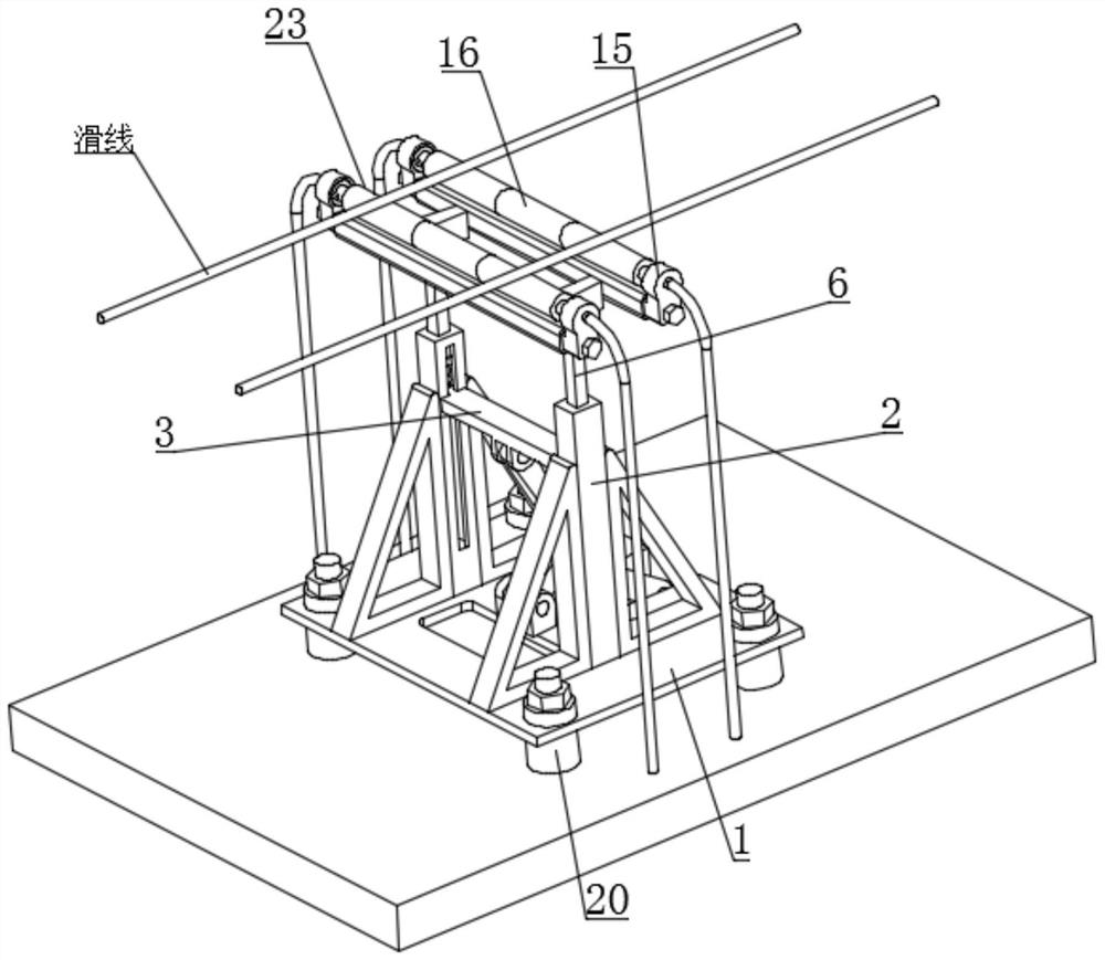
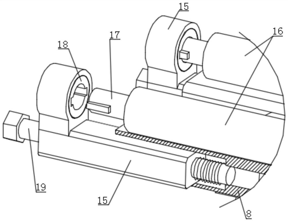
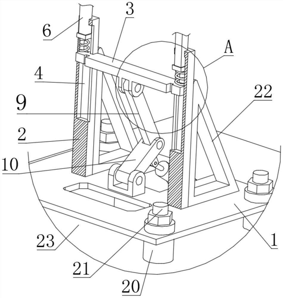
[0027] see Figure 1-12 , the present invention provides a technical solution: an adjustable power transmission system for a rail vehicle, comprising a bottom plate 1, after the bottom plate 1 is fixed on the rail vehicle, the bottom plate 1 is not in direct contact with the rail vehicle, thereby preventing electrical energy from passing from the bottom plate 1. Drainage to the rail vehicle, resulting in the occurrence of safety acci...


PUM


Abstract

The invention discloses an adjustable power transmission system for rail vehicles, comprising a bottom plate, a vertical pole is fixedly connected to the upper side of the bottom plate, and the two ends of the lifting pole respectively penetrate the side walls of the two vertical poles and are slidably connected to the chute Inside, the two ends of the lifting rod are connected with a sliding rod through a first spring, the upper side of the sliding rod is provided with a connecting block, the two sides of the connecting block are fixedly connected with electric contacts, and the two ends of the electric electric shock are electrically connected to cables respectively , the present invention makes the roller shaft contact the sliding line of the external contact net by sliding the sliding rod upwards. When the rail vehicle is running, when the roller shaft and the sliding wire are electrically connected, there is rolling friction between the roller shaft and the sliding wire. Therefore, on the basis of ensuring good performance, the wear of the roller shaft and the sliding wire is reduced, and the service life of the roller shaft and the sliding wire is increased. In addition, an adaptive arc groove is set to further reduce the wear and tear, and the split type of the roller shaft is adopted. Design reduces replacement cost and assembly difficulty.

Description

technical field [0001] The invention relates to the technical field of power transmission of rail vehicles, in particular to an adjustable power transmission system for rail vehicles. Background technique [0002] The electrical equipment that the rail vehicle obtains electrical energy from the catenary is installed on the roof of the rail vehicle to transmit the external power to the rail vehicle. The bow, that is, the friction contact between the pantograph and the sliding wire when the tram is running makes the vehicle electrify. This method makes the pantograph and the sliding wire wear extremely seriously during the operation of the electric vehicle, resulting in a short service life and a short replacement cycle. occurs, which in turn increases the cost of use, so we propose an adjustable power transmission system for rail vehicles. SUMMARY OF THE INVENTION [0003] The purpose of the present invention is to provide an adjustable power transmission system for rail v...

Claims


Application Information

Patent Timeline
Patent Type & Authority Patents(China)
IPC IPC(8): B60L5/06
CPCB60L5/06Y02T30/00
Inventor 赵德生甘艳
Owner NANJING INST OF RAILWAY TECH
Why Eureka
Try Eureka