
Large-scale stiffening-ring-spliced type triangular truss

A triangular and stiffening ring technology, which is applied to the fuselage frame, aerospace equipment, rigid spacecraft, etc., can solve the problems of difficult to use ring trusses, difficult manufacturing, complex configuration, etc., to improve the overall rigidity and improve the load deformation of the truss effect of ability

Active Publication Date: 2019-07-23
SHANGHAI JIAO TONG UNIV +1
View PDF8 Cites 9 Cited by
  • Summary
  • Abstract
  • Description
  • Claims
  • Application Information

AI Technical Summary

Problems solved by technology

[0007] Ju Su's "Composite Truss Bending Characteristics and Nonlinear Constraint Optimal Design" (Dissertation of National University of Defense Technology, Changsha, 2011) proposed a new type of all-composite truss structure—a composite truss structure with a triangular cross-section. It needs to be prepared by overall winding of fibers, and a 6m long truss has been prepared, and the bearing test research has been carried out, but it is difficult to apply to large ring trusses
[0008] Therefore, those skilled in the art are committed to developing a large-scale stiffened ring spliced ​​triangular truss to solve the existing problems of low precision, small rigidity, heavy weight, complex configuration, difficult manufacture, and difficulty in achieving large-scale

Method used


Image

  • Large-scale stiffening-ring-spliced type triangular truss
  • Large-scale stiffening-ring-spliced type triangular truss
  • Large-scale stiffening-ring-spliced type triangular truss

Examples


Embodiment Construction

[0032] The following describes the preferred embodiments of the present invention with reference to the accompanying drawings to make the technical content clearer and easier to understand. The present invention can be embodied in many different forms of embodiments, and the protection scope of the present invention is not limited to the embodiments mentioned herein.

[0033] In the drawings, components with the same structure are denoted by the same numerals, and components with similar structures or functions are denoted by similar numerals. The size and thickness of each component shown in the drawings are shown arbitrarily, and the present invention does not limit the size and thickness of each component. In order to make the illustration clearer, the thickness of parts is appropriately exaggerated in some places in the drawings.

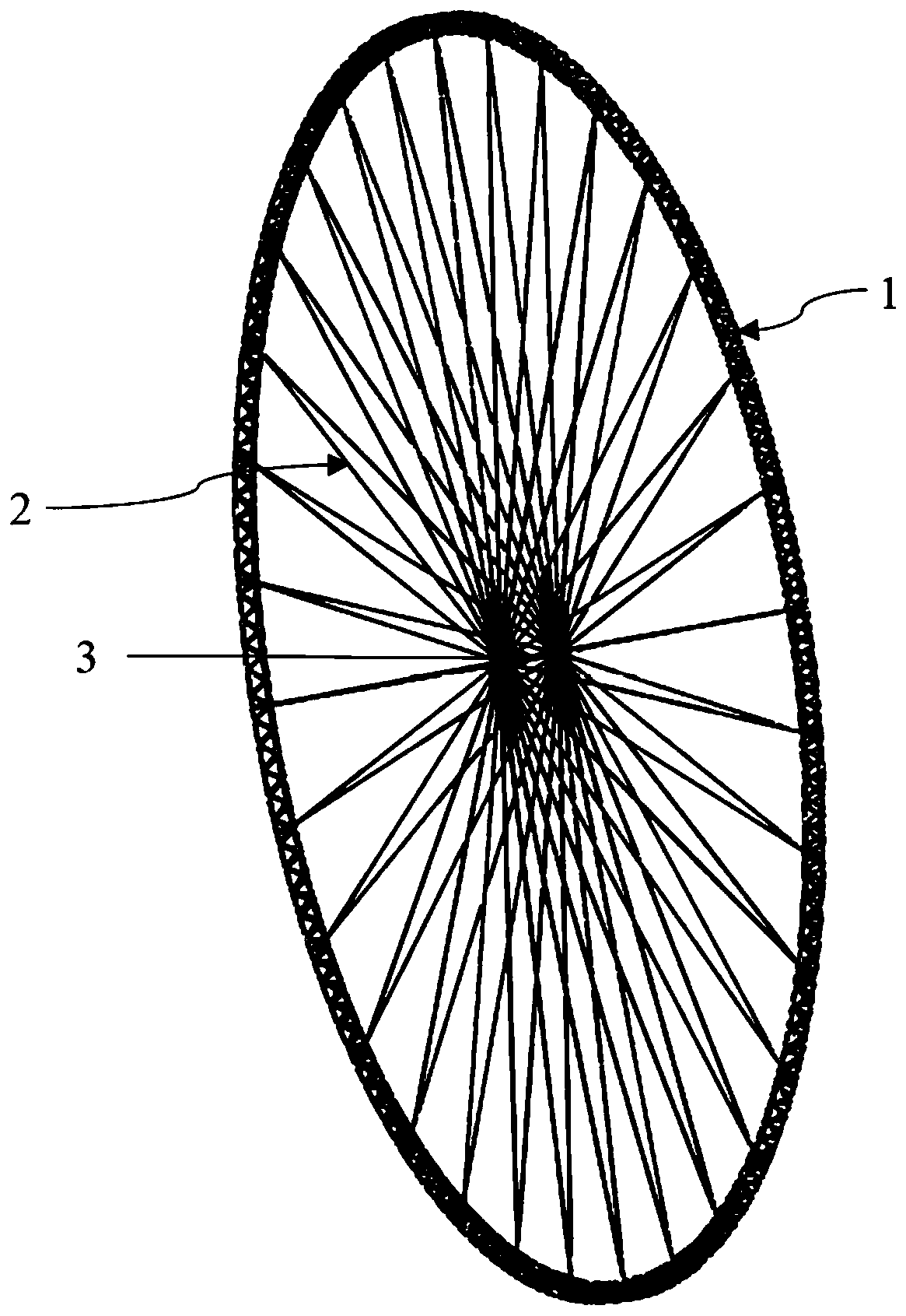
[0034] figure 1 It is a three-dimensional diagram of a large-scale stiffened ring spliced ​​triangular truss in a preferred embodiment of the...


PUM


Abstract

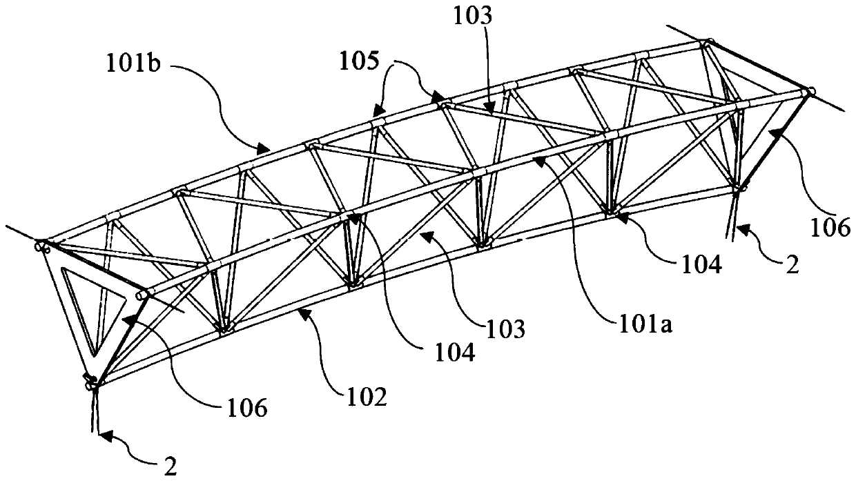
The invention discloses a large-scale stiffening-ring-spliced type triangular truss, and relates to the technical field of composite material structures. The triangular truss comprises a circular ringtriangular truss assembly, a radial pull rod assembly and a hub shaft assembly, and the circular ring triangular truss assembly and the hub shaft assembly are connected through the radial pull rod assembly, wherein the circular ring triangular truss assembly is formed by sequentially splicing a plurality of segment modules, and triangular connecting plates are arranged at two ends of the segmentmodules; the radial pull rod assembly comprises a rod body, hinged heads and fine adjustment joints, wherein the hinged heads and the fine adjustment joints are arranged at both ends of the rod body;and the hub shaft assembly comprises a hub shaft main body tube, a shuttle-shaped joint, an end mandrel, a hub connecting ring and a pressure-bearing ejecting-pushing sleeve, wherein the shuttle-shaped joint, the end mandrel, the hub connecting ring and the pressure-bearing ejecting-pushing sleeve are connected sequentially with the two ends of the hub shaft main body tube, the hub connecting ringis connected with the fine adjustment joint and connected with the triangular connecting plates of the segment modules through the radial pull rod assembly. The large-scale stiffening-ring-spliced type triangular truss can realize a large-scale composite material structure, stiffening rings can improve the overall rigidity of the truss, the load-bearing deformation ability and stability performance of the truss are improved, and the large-scale stiffening-ring-spliced type triangular truss can be applied to large-scale aircraft structures such as airships, unmanned aerial vehicles and the like and aerospace assembled type platforms.

Description

technical field [0001] The invention relates to the technical field of composite material structures, in particular to a large-scale stiffened ring spliced ​​triangular truss. Background technique [0002] Composite materials have the characteristics of light weight, high strength, high rigidity, fatigue resistance, etc., and are designable and manufacturable, and are widely used in the fields of aerospace and industrial products. In the field of aviation, the proportion of composite material structure is constantly increasing, accounting for nearly 40% of the current foreign advanced aircraft, and has become the core technical index to measure the advanced nature of aircraft. Composite truss structures or combined structures are also used in large satellite platforms, space platforms, and modern airship structures. [0003] Rainer Schütze's "Lightweight carbon fiber rods and truss structures" (Materials&Design, 1997, 18(4 / 6): 231-238) introduced a foam sandwich tube compos...

Claims


Application Information

Patent Timeline
IPC IPC(8): B64B1/08B64C1/06B64G1/22
CPCB64B1/08B64C1/061B64C1/065B64G1/22
Inventor 陈务军胡建辉赵兵王伟志杨钧徐建东
Owner SHANGHAI JIAO TONG UNIV
Learn More