
A non-conveying continuous steel bar automatic collection and bundling integration equipment

An automatic collection and continuous technology, which is applied to the parts and packaging of strapping machines, can solve the problems of manual pulling out of unloading vehicles, quantity counting errors, troublesome steel bar collection, etc., to achieve convenient counting, increase collection speed, and avoid The effect of rebar crossing

Active Publication Date: 2021-11-23
SHAOYANG GAOHUA IND & TRADE INDAL
View PDF0 Cites 0 Cited by
  • Summary
  • Abstract
  • Description
  • Claims
  • Application Information

AI Technical Summary

Problems solved by technology

[0002] The application range of steel bars covers almost all industries, and its main use is in the process of industrial production. At present, the steel bars used in construction, steel bar sales or other industries often need to be cut according to actual needs. In order to facilitate transportation, the cut steel bars need to be processed Bundling, the traditional cutting and bundling of steel bars are all done manually. In recent years, with the continuous upgrading of science and technology, steel bar cutting machines and bundling machines have been manufactured, but the cutting machines and bundling machines in the prior art can only They are used separately. After cutting the steel bars on the cutting machine, manually place the cut steel bars on the baler for bundling and packaging. Although this operation is more efficient than pure manual cutting and bundling, the equipment It occupies a large area and the collection of steel bars is troublesome, so the efficiency of the increase is limited. In addition, the existing baler only places multiple cut steel bars on the baler for bundling. Since the steel is heat-treated, when it is cut and dropped, It is inevitable to cross each other, it is difficult to pull out manually when unloading, and it is inevitable that there will be errors in the quantity counting

Method used


Image

  • A non-conveying continuous steel bar automatic collection and bundling integration equipment
  • A non-conveying continuous steel bar automatic collection and bundling integration equipment
  • A non-conveying continuous steel bar automatic collection and bundling integration equipment

Examples


Embodiment Construction

[0028] The present invention will be further described in detail below in conjunction with the accompanying drawings and embodiments.

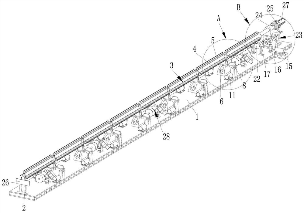
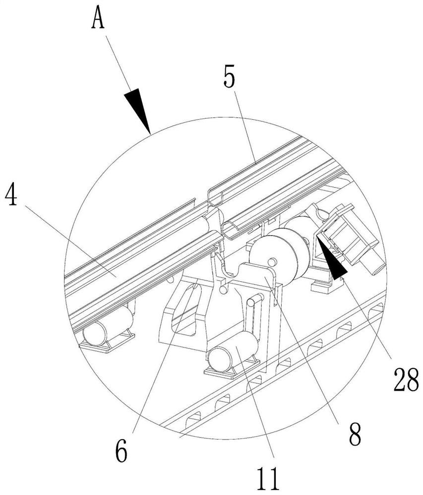
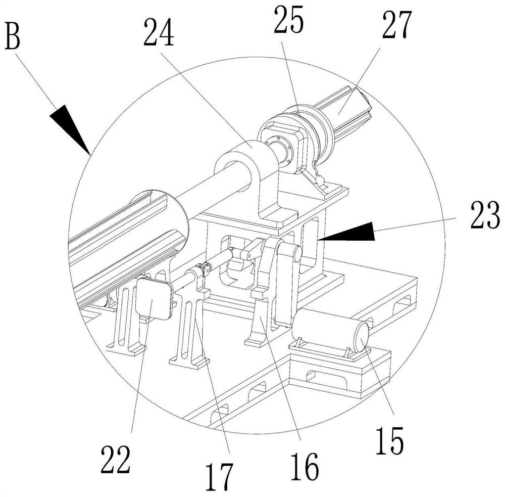
[0029] Such as Figure 1 to Figure 5 As shown, a non-conveying continuous steel bar automatic collection and bundling integration equipment includes a bottom plate 1, a driving device is provided on the bottom plate 1, and the output end of the driving device is connected with a material receiving device for connecting cut steel bars. device, the other end of the material receiving device is connected with a connecting frame 2, and the side of the material receiving device is correspondingly provided with a turning device and a bundling device 28, and a plurality of steel bars can be aligned between the driving device and the material receiving device. When in use, the present invention is arranged under the steel bar cutting equipment. When the steel bar is cut off, it falls on the material receiving device. At the same time, the drive motor ...


PUM


Abstract

The invention relates to a non-conveying continuous steel bar automatic collection and bundling integration equipment, which includes a bottom plate and a driving device. The output end of the driving device is connected to a material receiving device, and the other end of the material receiving device is connected to a connecting frame. There is a turning device and a bundling device, and a straightening device is installed between the driving device and the material receiving device. When in use, when the steel bar is cut, it falls and is collected on the material receiving device, and the driving device drives the material receiving device to rotate. , slide the steel bars to the turning device and the bundling device one after another, then straighten the steel bars through the straightening device, and finally roll and turn the multiple steel bars through the turning device, so that the bundling device can bind the multiple steel bars tightly, so that The cut steel bars do not need to be transported to other stations, and the continuous automatic drop collection, sorting, and bundling operations can be realized at the same station, which can effectively improve work efficiency, solve loading and unloading problems, and facilitate counting during use. And guarantee the bundling quality.

Description

technical field [0001] The invention relates to the technical field of steel bar processing, in particular to a non-conveying continuous steel bar automatic collection and bundling integration equipment. Background technique [0002] The application range of steel bars covers almost all industries, and its main use is in the process of industrial production. At present, steel bars used in construction, steel bar sales or other industries often need to be cut according to actual needs. In order to facilitate transportation, the cut steel bars need to be Bundling, the traditional cutting and bundling of steel bars are all done manually. In recent years, with the continuous upgrading of science and technology, steel bar cutting machines and bundling machines have been manufactured, but the cutting machines and bundling machines in the prior art can only They are used separately. After cutting the steel bars on the cutting machine, manually place the cut steel bars on the tying ...

Claims


Application Information

Patent Timeline
Patent Type & Authority Patents(China)
IPC IPC(8): B65B13/18B65B27/10B65B35/58
CPCB65B13/18B65B27/10B65B35/58
Inventor 王高华王文浩王文韬
Owner SHAOYANG GAOHUA IND & TRADE INDAL
Learn More