Inductive automatic flushing tank

A technology for flushing water tanks and water tanks, which is applied to flushing equipment with water tanks, water supply devices, buildings, etc., which can solve the problems of high cost of use of induction flushing devices, easy to be carried on the body, cross-infection, and inconvenience to users, etc., to achieve realization The effect of accessibility

Active Publication Date: 2019-07-23
福建省博亿水暖科技有限公司
View PDF7 Cites 0 Cited by
  • Summary
  • Abstract
  • Description
  • Claims
  • Application Information

AI Technical Summary

Problems solved by technology

[0002] Most of the toilet flushing tanks used in the restrooms of some public places are manually flushing. The structure of this manual flushing tank mainly includes: a water tank body, the water tank body is provided with buttons, and the lower end of the water tank body is provided with an inlet. The water inlet and the water outlet, the water inlet is connected with a water inlet pipe, the upper end of the water inlet pipe is provided with a float valve for controlling the water intake, and the water outlet can be moved up and down to be provided with a water stop ball plug. A starting lever is connected, and the other end of the starting lever is connected with the button. An overflow pipe is also arranged in the water tank body. The overflow pipe is vertically installed in the water tank body. The water outlet is connected; the manual flushing tank, due to too many people using it, will inevitably breed bacteria and viruses on the flushing tank. These bacteria and viruses cannot be washed with clean water, so they are easily carried on the body and cross-infected, endangering the human body healthy
[0003] In order to solve the above technical problems, there are some induction flushing devices on the market. Although the problem of cross-infection of bacteria and viruses can be avoided, when the induction flushing device is damaged, it cannot be used anymore, and the entire induction flushing device must be repaired or replaced. In this way, the use cost of the induction flushing device is high, and the toilet cannot be used normally during the repair or replacement of the induction flushing device, which causes great inconvenience to the user

Method used


Image

  • Inductive automatic flushing tank
  • Inductive automatic flushing tank
  • Inductive automatic flushing tank

Examples


Embodiment 1

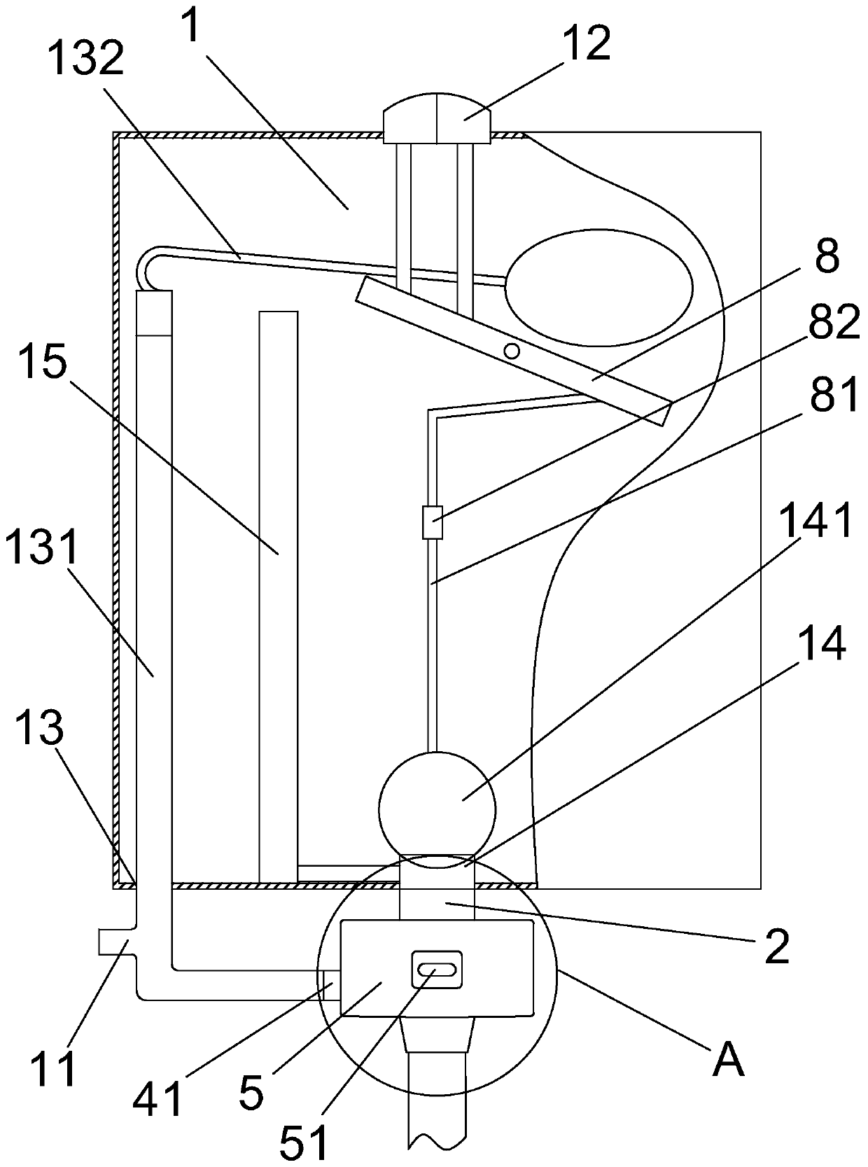
[0021] reference Figure 1 to Figure 2 , The embodiment of the present invention discloses a manual flushing water tank, including a water tank body 1, the water tank body 1 is provided with a button 12, the lower end of the water tank body 1 is provided with a water inlet 13, a water outlet 14, the water inlet 13 is connected to the upper end of a water inlet pipe 131, the upper end of the water inlet pipe 131 is provided with a float valve 132 for controlling the amount of water inflow, the lower end of the water inlet 13 is connected to a water supply pipe 11, and the water outlet 14 is movable up and down and is provided for opening Or a water stop ball plug 141 that blocks the water outlet, the water tank body 1 is provided with a moving device that drives the water stop ball plug 141 to move up and down. The moving device includes a starter lever 8, the middle of the starter lever 8 is rotatably arranged In the water tank body 1, one end of the start lever 8 is connected ...

Embodiment 2

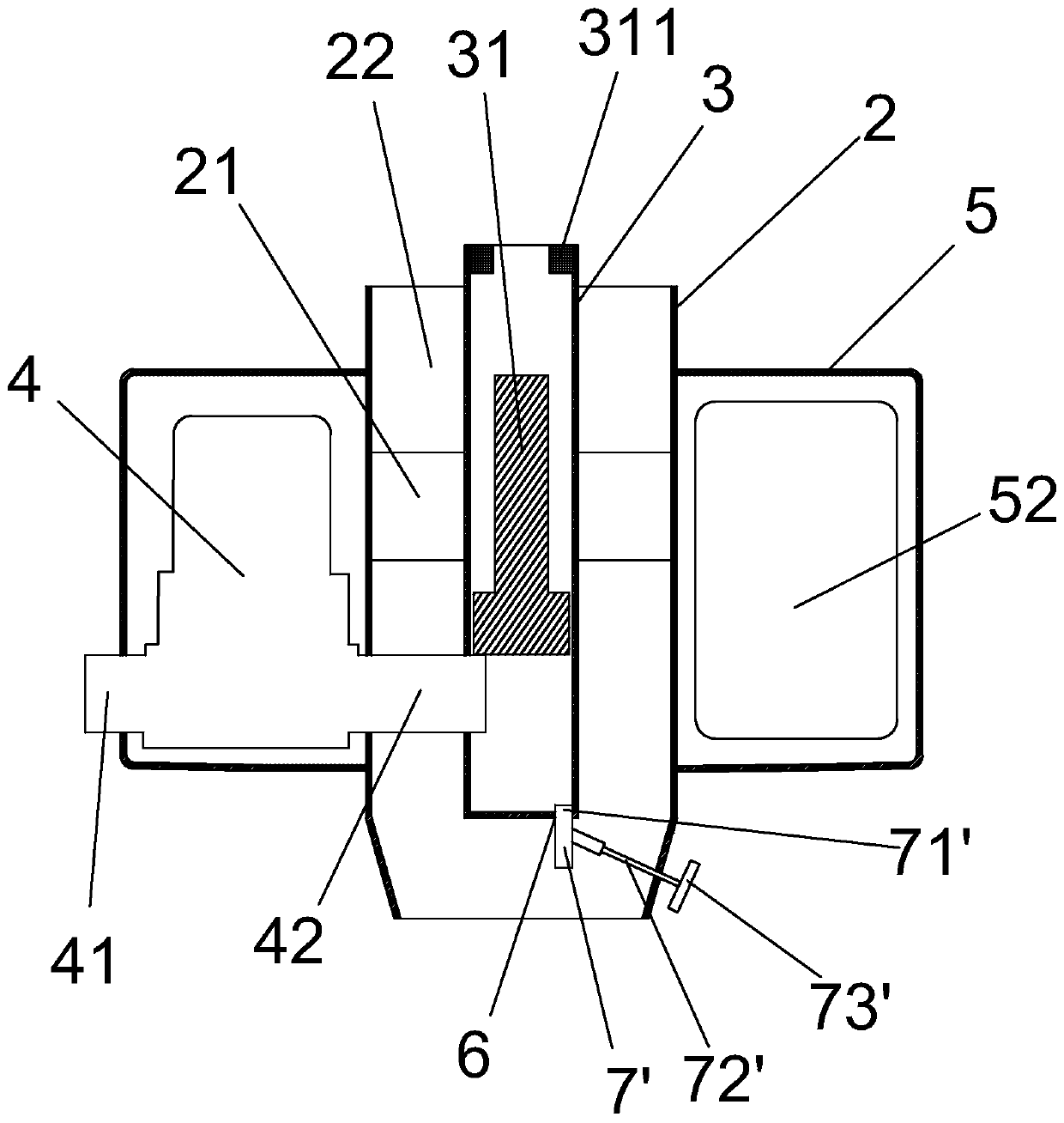
[0023] reference image 3 Based on the foregoing solution, in actual operation, the pressure regulating device may also include a self-pressure pressure regulating valve 7', the self-pressure pressure regulating valve 7'is arranged at the lower end of the cavity 3, and the self-pressure The water inlet 71' of the pressure regulating valve 7'is in communication with the cavity 3, and the regulating rod 72' of the self-pressing pressure regulating valve 7'penetrates the wall of the outlet pipe 2, and the regulating rod The free end of 72' is provided with a rotating handle 73'.

[0024] The working principle of the present invention: the sensor fixed on the shell is used to sense whether flushing is needed. When the sensor senses that someone is using the toilet, it will generate an electrical signal and transmit it to the solenoid valve after the person leaves. The solenoid valve is receiving When the electric signal is received, the valve is opened to allow the water to enter the...


PUM


Abstract

The invention provides an inductive automatic flushing tank reasonable in structural design and easy to operate. The flushing tank comprises a water tank body, the water tank body is provided with a button, the lower end of the water tank body is provided with a water inlet and a water outlet, a water inlet pipe is connected to the upper end of the water inlet, and the upper end of the water inletpipe is provided with a floating ball valve for controlling a water inlet amount; a water supply pipe is connected to the lower end of the water inlet, and the water outlet is provided with a water stop ball plug which can move up and down and is used for opening or blocking the water outlet; the water tank body is internally provided with a moving device driving the water stop ball plug to moveup and down, a water outlet pipe is connected to the water outlet and is internally provided with a rising and falling device for jacking the water stop ball plug, the rising and falling device comprises a cavity formed in the lower end of the water stop ball plug, the cavity is fixedly connected with the inner wall of the water outlet pipe, a channel for water to flow out is reserved between thecavity and the inner wall of the water outlet pipe, a piston rod capable of sliding up and down is arranged in the cavity, and the water outlet pipe is provided with a driving device for driving the piston rod to slide up and down.

Description

Technical field [0001] The invention relates to the technical field of daily necessities, in particular to an induction type automatic flushing tank. Background technique [0002] Most of the toilet flushing tanks used in toilets in some public places are manually flushed. The structure of this manual flushing tank mainly includes: a water tank body, the water tank body is provided with a button, and the lower end of the water tank body is provided with an inlet Water inlet and water outlet, the water inlet is connected with a water inlet pipe, the upper end of the water inlet pipe is provided with a float valve for controlling the amount of water inflow, the water outlet can be moved up and down with a water stop ball plug, and the water stop ball plug is on A starter lever is connected, the other end of the starter lever is connected to the button, the water tank body is also provided with an overflow pipe, the overflow pipe is erected in the water tank body, and the lower end ...

Claims


Application Information

Patent Timeline
Patent Type & Authority Applications(China)
IPC IPC(8): E03D5/10E03D1/00E03D1/30E03D1/33
CPCE03D1/00E03D1/30E03D1/302E03D1/33E03D5/105
Inventor 陈立境陈根琛
Owner 福建省博亿水暖科技有限公司
Why Eureka
Try Eureka