Fatigue test device with controllable application of multiaxial stress on welded seam and its application method

A technology of fatigue test and fatigue testing machine, which is applied in the field of fatigue test devices with controllable application of multiaxial stress on welds, can solve the problems of being unable to represent multiaxial fatigue performance and realize loading of controllable multiaxial fatigue stress, and achieve The effect of avoiding repeated handling, avoiding damage, and simplifying the test process

Active Publication Date: 2021-05-11
HOHAI UNIV
View PDF14 Cites 0 Cited by
  • Summary
  • Abstract
  • Description
  • Claims
  • Application Information

AI Technical Summary

Problems solved by technology

The patents "Mechanical Specimen Fatigue Testing Machine and Its Test Method (201110416431.2)" and "Fatigue Test Device Considering the Coupling Effect of Steel Bridge Deck and Pavement (201611159177.1)" proposed a fatigue test device based on the vibration-type fatigue loading method. But none of them can achieve controllable multiaxial fatigue stress loading
Although the obtained test results can better reflect the fatigue performance under the uniaxial stress state, they cannot represent the actual multiaxial fatigue performance of the structure.

Method used


Image

  • Fatigue test device with controllable application of multiaxial stress on welded seam and its application method
  • Fatigue test device with controllable application of multiaxial stress on welded seam and its application method
  • Fatigue test device with controllable application of multiaxial stress on welded seam and its application method

Examples


Embodiment 1

[0052] Example 1: Fatigue loading of the axial initial stress of the weld and the initial tensile stress in the direction perpendicular to the weld

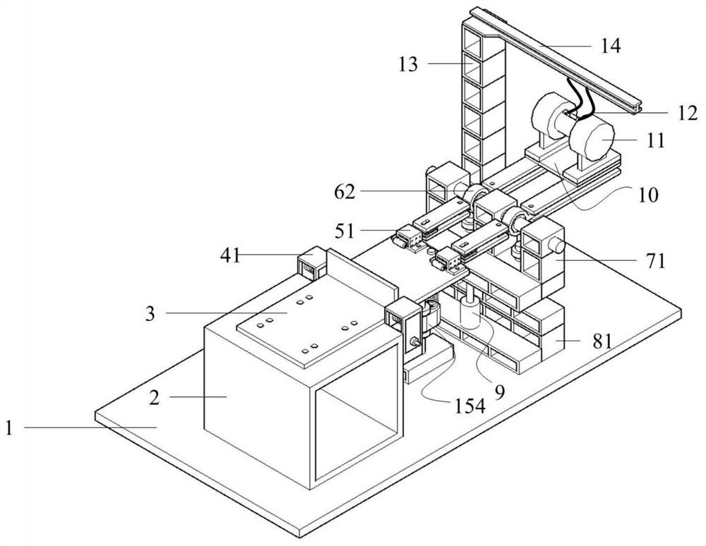
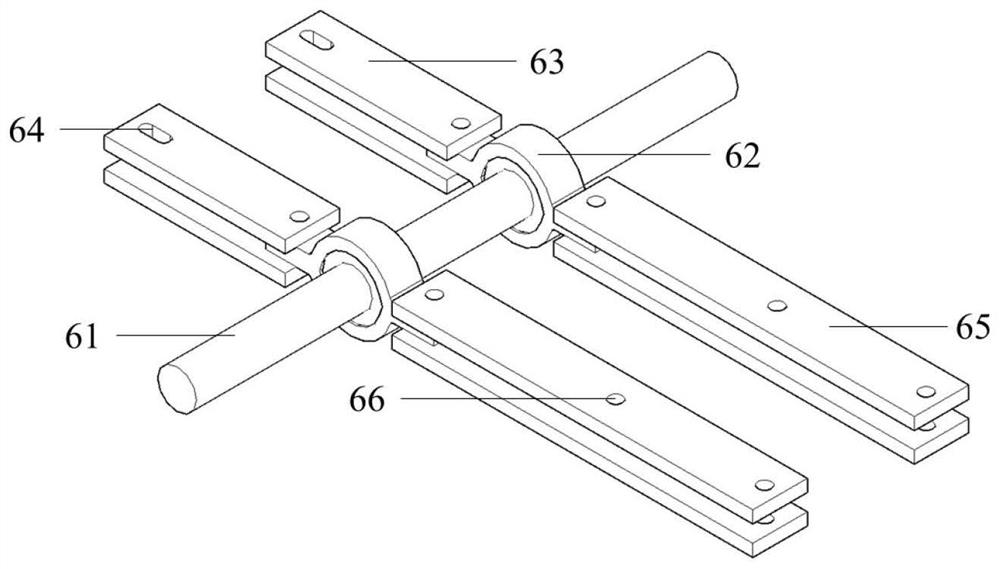
[0053] see Figure 1 to Figure 12, complete the frame, test piece, weld axial initial stress application system, vertical weld initial stress application system, transverse hinge system, lever force transmission system, height adjustable base and safety suspension fatigue loading system as required installation.

[0054] Paste three-way strain rosettes at the stress measuring point of the weld seam concerned, such as the nominal stress measuring point 10mm away from the weld toe, where the strain gauge at 0° is horizontal to the weld, and the strain gauge at 90° is perpendicular to the weld.

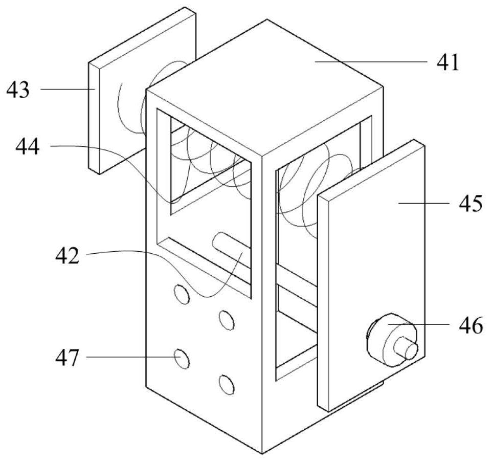
[0055] Synchronously adjust the adjusting nut 46 of the axial initial stress application system on both sides of the weld seam of the test piece, and observe the reading of the 0° strain gauge at the same time. During the adjustment proces...

Embodiment 2

[0058] Example 2: Fatigue loading of the axial initial stress of the weld seam and the initial compressive stress of the vertical weld seam

[0059] see Figure 1 to Figure 11 and Figure 13 , complete the frame, test piece, weld axial initial stress application system, vertical weld initial stress application system, transverse hinge system, lever force transmission system, height adjustable base and safety suspension fatigue loading system as required installation.

[0060] Paste three-way strain rosettes on the weld stress measuring point of concern, such as the nominal stress measuring point 10mm away from the weld toe, where the 0° strain gauge is horizontal to the weld, and the 90° strain gauge is perpendicular to the weld.

[0061] Synchronously adjust the adjusting nut 46 of the axial initial stress application system on both sides of the weld seam of the test piece, and observe the reading of the 0° strain gauge at the same time. During the adjustment process, ensur...


PUM


Abstract

The invention discloses a fatigue test device for controllable application of weld multiaxial stress and its application method. system, a height-adjustable base and a safety suspension type fatigue loading system; an application method based on the above-mentioned device, including the following steps: pasting the initial load control strain gauge; installing the test piece; pre-applying the axial initial stress of the weld seam; perpendicular to the weld seam direction Initial stress pre-applying; fatigue loading of weld multiaxial stresses. The present invention can simulate the initial axial stress of the multi-axial stress weld seam of steel structure and the application of the initial stress perpendicular to the weld seam, and ensure the precise and controllable magnitude of the applied initial stress. Based on the test device and application method of the present invention, the The test results can accurately reflect the fatigue performance of the weld under the multiaxial stress state, and the test results are closer to the actual operating conditions, providing support for improving the accuracy of the fatigue test results.

Description

technical field [0001] The invention relates to a fatigue test device and an application method thereof, in particular to a fatigue test device with controllable application of weld multiaxial stress and an application method thereof. Background technique [0002] Steel structures have been more and more widely used in road bridges, civil buildings, offshore platforms and other structures. However, due to the complexity of steel structure components, welding is still the most important way to connect various components. But for an overall structure, the welding workload is huge, and welding defects (such as welding bumps, inclusions, etc.) are unavoidable. Under the coupling effect of welding residual stress and external repeated load, fatigue cracking of weld seam occurs from time to time. For example, the fatigue cracks in the steel box girder welds of many domestic cross-river steel bridges have reached more than a thousand. The continuous expansion of fatigue cracks w...

Claims


Application Information

Patent Timeline
Patent Type & Authority Patents(China)
IPC IPC(8): G01N3/32G01N3/02
CPCG01N3/02G01N3/32G01N2203/0005G01N2203/0073
Inventor 吉伯海傅中秋王秋东姚悦
Owner HOHAI UNIV
Why Eureka
Try Eureka