
Power fault monitoring system and method

A power failure and monitoring system technology, applied in the direction of circuit devices, electrical components, etc., can solve the problems of high degree of automation and intelligence, single structure and function, and achieve the effect of high degree of automation and intelligence

Pending Publication Date: 2019-07-23
SHOUGANG JINGTANG IRON & STEEL CO LTD
View PDF10 Cites 0 Cited by
  • Summary
  • Abstract
  • Description
  • Claims
  • Application Information

AI Technical Summary

Problems solved by technology

[0004] The embodiment of the present application provides a power fault monitoring system and method, which solves the problem that the power monitoring device in the prior art has a single structure and function, can only monitor data, and then relies on manual data recording and analysis to achieve fault monitoring. Integration with analysis, high degree of automation and intelligence

Method used


Image

  • Power fault monitoring system and method
  • Power fault monitoring system and method
  • Power fault monitoring system and method

Examples


Embodiment 1

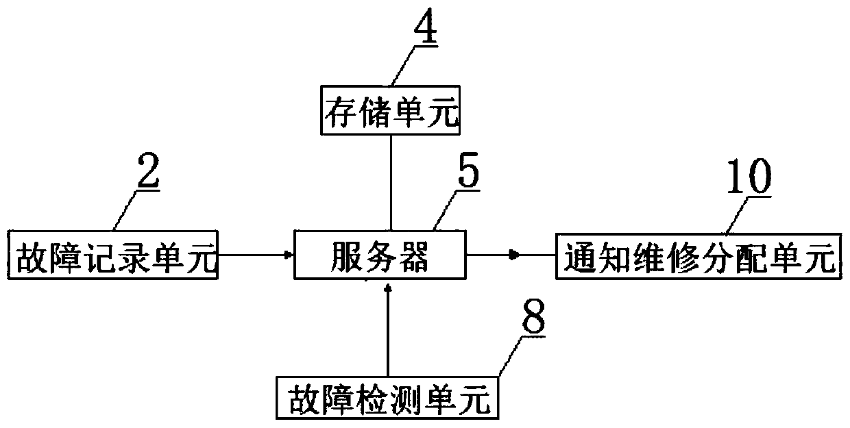
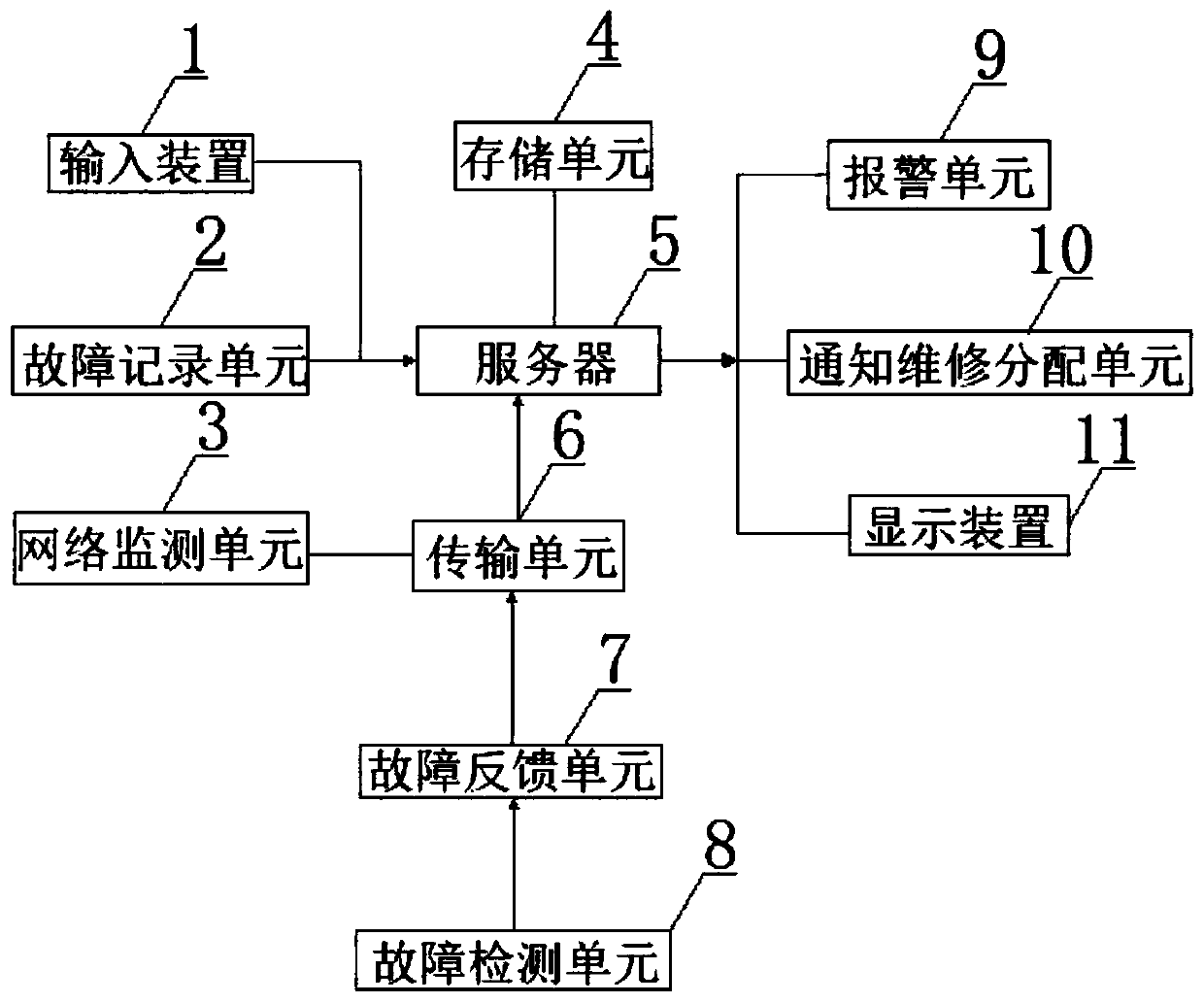
[0041] Such as figure 1 As shown, in this embodiment, a power failure monitoring system for a steel company includes a server 5, a failure detection unit 8, a notification maintenance distribution unit 10, a failure recording unit 2, a storage unit 4; the failure detection unit 8. The server 5 is communicatively connected to the server 5 for monitoring fault information, and the fault information is transmitted to the server 5 for fault analysis; the server 5 is communicatively connected to the notification maintenance distribution unit 10 for fault analysis The analysis result is sent to the notification maintenance distribution unit 10; the notification maintenance distribution unit 10 is used to allocate maintenance personnel to perform maintenance inspections according to the failure analysis results; the failure recording unit 2 is communicatively connected to the server 5 for use To record the fault information and the fault analysis result; the storage unit 4 is communica...

Embodiment 2

[0048] In this embodiment, on the basis of the first embodiment, the fault feedback unit 7 is also communicatively connected between the server 5 and the fault detection unit 8 for the working conditions of simultaneous monitoring of multiple points in the power system. It collects the monitoring data from multiple monitoring points, converts the monitoring data according to the transmission requirements, and then transmits it to the server 5.

Embodiment 3

[0050] In this embodiment, on the basis of the second embodiment, in order to monitor abnormalities in the data transmission process, the fault feedback unit 7 and the server 5 are connected through a transmission unit 6, and the transmission unit 6 is communicatively connected with a network monitoring unit.

[0051] Specifically, in this embodiment, the network monitoring unit 3 may be an existing network monitoring device or system.


PUM


Abstract

The invention discloses a power fault monitoring system and method, and relates to the technical field of steel refining. The power fault monitoring system comprises a server, a fault detection unit,a notification maintenance allocation unit, a fault recording unit and a storage unit, wherein the fault detection unit is in communication connection with the server and is used for monitoring faultinformation and transmitting the fault information to the server for fault analysis, the server is in communication connection with the notification maintenance allocation unit and is used for feedingback a fault analysis result to a maintainer by the notification maintenance allocation unit, and the server is also in communication connection with the fault recording unit and the storage unit andis used for recording and storing the fault information and fault analysis data. By the power fault monitoring system, the problems that a power monitoring device in the prior art is simple in structure function, only data is monitored and subsequent data recording and analysis is completely dependent on manual operation are solved, integration of fault monitoring and analysis is achieved, and automation and intelligence are high.

Description

Technical field [0001] The invention relates to the technical field of steel refining, in particular to a power failure monitoring system and method for steel companies. Background technique [0002] With the development of industry, the use of electricity has become more and more extensive. The transmission of electricity requires the deployment of dense power grids in cities. In order to facilitate the management of urban electricity consumption and rational distribution of electricity, it is necessary to use a power monitoring system for management, like steel companies With the continuous expansion of voltage levels and grid capacity of this kind of enterprises with huge power consumption, ensuring their reliable operation is more and more important for maintaining the safety and stability of the entire power system. On-line monitoring technology of power equipment has increasingly shown its importance and necessity. Sex. [0003] Power monitoring devices are of great signific...

Claims


Application Information

Patent Timeline
Patent Type & Authority Applications(China)
IPC IPC(8): H02J13/00
CPCH02J13/0017
Inventor 刘正发范军沈军燕飞李士栋蔡志全刘连凯王延明杨海超
Owner SHOUGANG JINGTANG IRON & STEEL CO LTD
Learn More