Aircraft engine fan blade cleaning system

A technology for aircraft engines and fan blades, applied to mechanical conveyors, conveyors, cleaning methods and appliances, etc., can solve problems such as long working hours, high labor intensity, hidden safety hazards, etc., to improve work efficiency, improve work environment, The effect of broad social benefits

Active Publication Date: 2021-06-29
CIVIL AVIATION UNIV OF CHINA
View PDF0 Cites 2 Cited by
  • Summary
  • Abstract
  • Description
  • Claims
  • Application Information

AI Technical Summary

Problems solved by technology

[0002] Aircraft engine blades are an important part of aircraft engine engines, and have strict requirements on their fatigue resistance, high temperature resistance, and corrosion resistance. Since aircraft engine blades work at high temperatures for a long time, disulfide will remain on the pressure surface coating. A mixture of molybdenum and some other stains, which can increase the corrosion of aircraft engine blades and pose a safety hazard if not cleaned regularly
At present, there are few mature and effective automatic aircraft engine blade cleaning methods at home and abroad, and most of them use manual methods for cleaning in China.
The cleaners use isopropanol as the cleaning material, and use brushes to repeatedly scrub the blades of the aircraft engine. Obviously, the working hours are long and the labor intensity is high.
Moreover, isopropanol is a colorless and transparent organic compound, which has certain carcinogenicity and will cause great harm to the human body.

Method used


Image

  • Aircraft engine fan blade cleaning system
  • Aircraft engine fan blade cleaning system
  • Aircraft engine fan blade cleaning system

Examples


Embodiment Construction

[0020] The present invention will be described in detail below in conjunction with the accompanying drawings and specific embodiments.

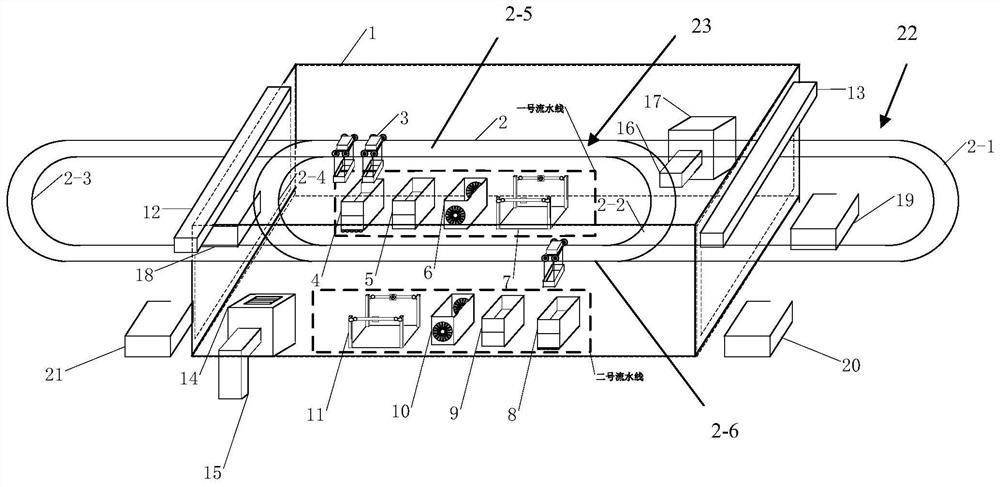
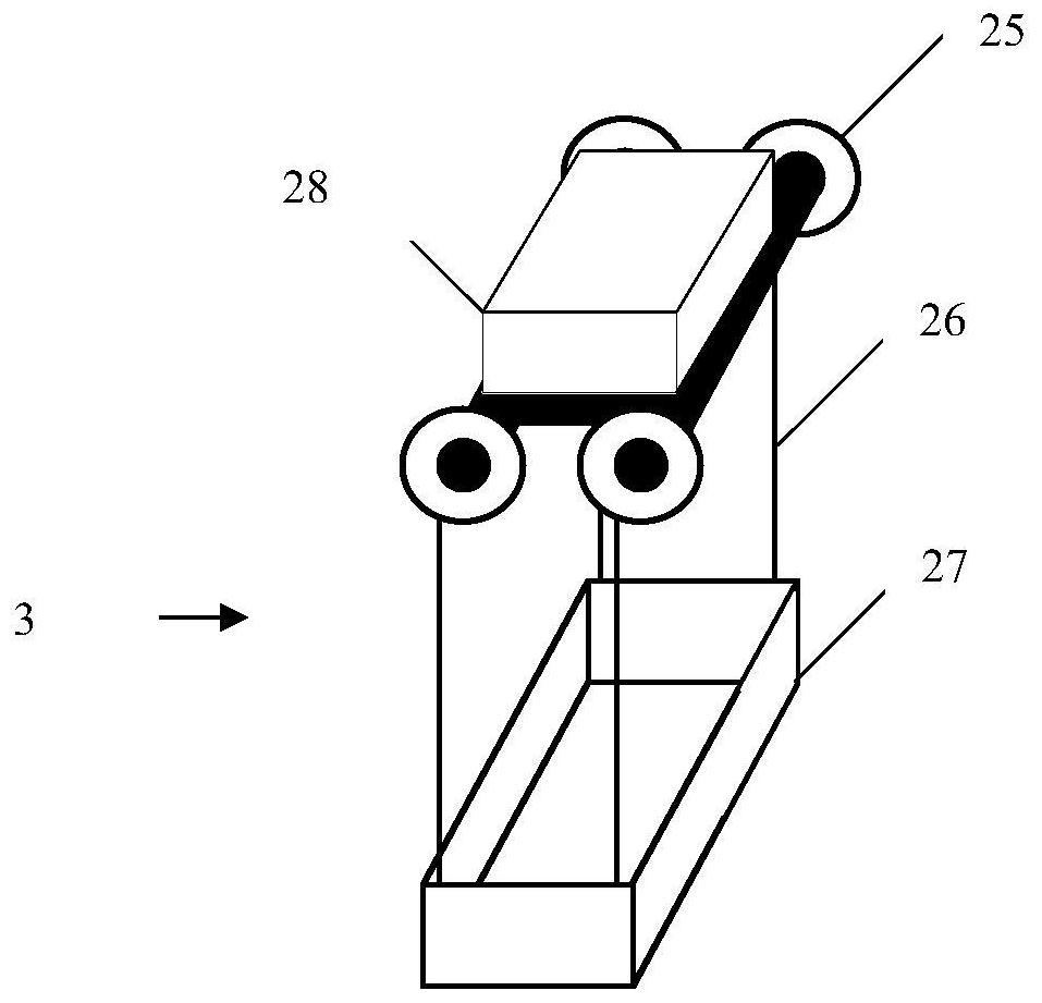
[0021] Such as figure 1 As shown, the aircraft engine fan blade cleaning system provided by the present invention includes a casing 1, a pulley track 2, a loading electric rail car 3, a first air curtain machine 12, a second air curtain machine 13, a blower fan 14, a gas filtering device 17, No. 1 assembly line and No. 2 assembly line; wherein, the housing 1 is a cuboid structure, and the front and rear ends are open; the first air curtain machine 12 and the second air curtain machine 13 are respectively installed on the upper part of the front and rear ports of the housing 1; the pulley The track 2 is composed of a long loop track 22 and a short loop track 23. The long loop track 22 and the short loop track 23 are elongated circular structures, and the two side tracks of the short loop track 23 are connected with the two sides of the long lo...


PUM


Abstract

The utility model relates to an aircraft engine fan blade cleaning system. It includes a casing, a pulley track, a load-carrying electric rail car, a first air curtain machine, a second air curtain machine, a blower, a gas filter device, a No. 1 assembly line and a No. 2 assembly line. Effects of the invention: the steps of manual cleaning can be eliminated, the health of workers can be protected, and humanistic care can be embodied; cleaning efficiency can be improved, and economic benefits can be improved. Provides an efficient automatic cleaning method, simplifies the cleaning procedure, shortens the working time of the cleaning process, ultimately saves labor costs, improves work efficiency, and brings considerable economic benefits to the maintenance company. It can improve the working environment of the maintenance staff, improve the corresponding work efficiency, demonstrate the level of civil aviation technology, and have extensive social benefits. The development of this system will take a big step towards a more humanized and intelligent direction, and it will be a new attempt and exploration for future maintenance work and maintenance companies.

Description

technical field [0001] The invention belongs to the technical field of aviation equipment, in particular to an aircraft engine fan blade cleaning system Background technique [0002] Aircraft engine blades are an important part of aircraft engine engines, and have strict requirements on their fatigue resistance, high temperature resistance, and corrosion resistance. Since aircraft engine blades work at high temperatures for a long time, disulfide will remain on the pressure surface coating. A mixture of molybdenum and some other stains, which can increase the corrosion of aircraft engine blades and pose a safety hazard if not cleaned regularly. At present, there are few mature and effective automatic aircraft engine blade cleaning methods at home and abroad, and most of them use manual methods for cleaning in China. The cleaners use isopropanol as the cleaning material, and use brushes to repeatedly scrub the blades of the aircraft engine. Obviously, the working hours are l...

Claims


Application Information

Patent Timeline
Patent Type & Authority Patents(China)
IPC IPC(8): B08B3/08B08B13/00B65G35/00
CPCB08B3/08B08B13/00B65G35/00
Inventor 牛国臣朱通张莉莎范宇
Owner CIVIL AVIATION UNIV OF CHINA
Why Eureka
Try Eureka