
Design method of chip breaking type milling cutter

A design method and milling cutter technology, which is applied to milling cutters, milling machine equipment, metal processing equipment, etc., can solve problems such as machine adjustment, low efficiency, and poor product quality consistency

Active Publication Date: 2019-07-26
厦门鸿鹭联创工具有限公司
View PDF7 Cites 3 Cited by
  • Summary
  • Abstract
  • Description
  • Claims
  • Application Information

AI Technical Summary

Problems solved by technology

The main difficulty of this design method is: due to the lack of an effective design method, the parameter design of the milling cutter can only be determined by the previous cutter shape, through machine adjustment, fine-tuning the parameters of the grinding wheel, and controlling the processing flow of the right 2 helix angle and the right 2 motor angle To match the target parameters, it often requires multiple round-trip operations such as multiple tool repairs, test parameters, re-dressing the grinding wheel, and re-trimming. It takes a long time to adjust the machine, and the efficiency is extremely low. Whether the parameters meet the standards is often based on processing experience. Human judgment, product quality consistency is poor

Method used


Image

  • Design method of chip breaking type milling cutter
  • Design method of chip breaking type milling cutter
  • Design method of chip breaking type milling cutter

Examples


Embodiment Construction

[0027] Such as figure 1 As shown, the present invention is a design method of a chip breaking type milling cutter, comprising the following steps:

[0028] Step (1): If figure 1 As shown, determine the target parameter requirement: the target parameter of RRC milling cutter 10 is: figure 1 The side groove depth h, the tooth width C1, the overlap D, and the groove length C2;

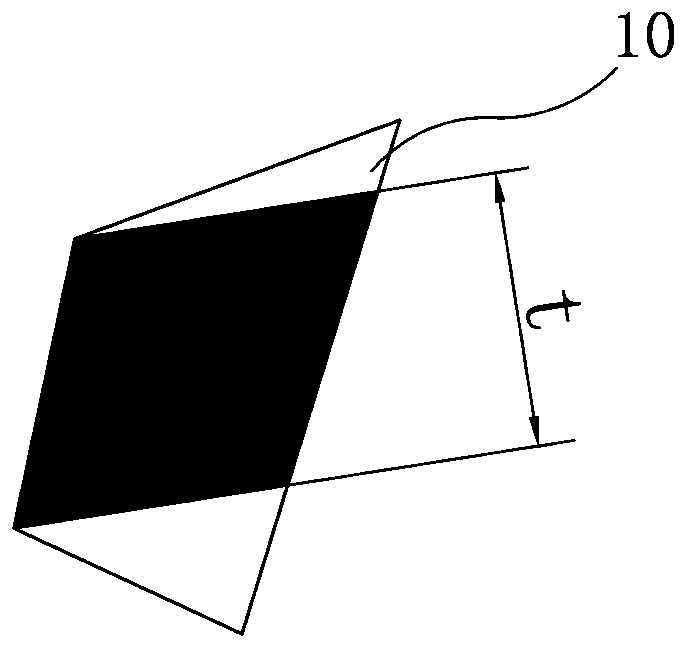
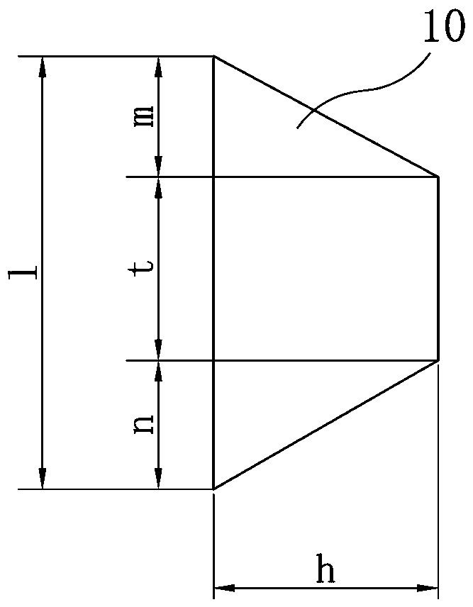
[0029] Step (2): According to the front view of the milling cutter 10 right-handed 2 grooves (such as figure 2 shown) and side view (as image 3 shown), and compare the cutting marks of the right-handed 2 grinding wheel on the groove: figure 2 Middle t is the width of the cutting area on the 0° face of the grinding wheel; image 3 Among them, h: depth of right-handed side groove; l: cutting width of grinding wheel in spiral direction; t: width of grinding wheel face at 0°; n: cutting width of grinding wheel at angle 1; m: cutting width of grinding wheel at angle 2;

[0030] Step (3): according to ...


PUM


Abstract

The invention discloses a design method of a chip breaking type milling cutter. The design method includes the following steps that target parameter requirements are determined, the cutting marks of right-handed rotation 2 grinding wheels on a groove type are compared, the widths of the grinding wheels participating in grinding are calculated, the longitudinal cutting values of the grinding wheelson rods are calculated, the cutting actual widths of the grinding wheels are calculated, right-handed rotation 2 groove lengths are calculated, groove distances are calculated, actual values of the groove distances are calculated, and integrated calculation is carried out according to the parameters acquired in the steps. As geometric correlation exists between RRC milling cutter right-handed rotation 2 parameters, the forming result of a cutter type is simulated with the help of the geometric correlation and the machining principle of the cutter type, a complete set of formulas are formulated, when the parameters are designed, corresponding cutter type parameters are simulated according to input of different influence factors, finally the cutter type parameters are matched with needed equipment set parameters, and the design method has the beneficial effects of being short in machining time and high in machining efficiency.

Description

technical field [0001] The invention relates to a cutting tool, in particular to a design method of a chip-breaking milling cutter. Background technique [0002] RRC milling cutter has the characteristics of high dimensional accuracy, high feed speed, and long life. It is mainly used in high-end PCB boards such as HDI, Server, and Module. With the development of the industry, the application proportion of high-end boards in the PCB industry is increasing. Therefore, the proportion of RC milling cutters in our department's production and sample making is also increasing. [0003] The current design method: determine the parameters required for processing the plate based on experience, and then continuously correct the parameters of the grinding wheel, helix angle, and motor angle to achieve the target knife shape parameters. The main difficulty of this design method is: due to the lack of an effective design method, the parameter design of the milling cutter can only be dete...

Claims


Application Information

Patent Timeline
IPC IPC(8): B23C5/10
CPCB23C5/10B23C2210/48
Inventor 罗茂华魏志杰柯建泉王长泰
Owner 厦门鸿鹭联创工具有限公司
Learn More