Railway locomotive braking system and emergency redundant passage detection method thereof

A braking system and rail locomotive technology, applied in the direction of braking safety systems, brakes, brake components, etc., can solve the problems of adverse effects of safe and efficient operation of the braking system, low operating efficiency, cumbersome and inconvenient operation, etc., and achieve detection and judgment The results are accurate and reliable

Active Publication Date: 2019-07-26
QINGDAO SRI TECH CO LTD
View PDF9 Cites 14 Cited by
  • Summary
  • Abstract
  • Description
  • Claims
  • Application Information

AI Technical Summary

Problems solved by technology

[0003] Since the distribution valve passage and the emergency redundant passage of the existing rail locomotive braking system share the same brake cylinder sensor, when it is necessary to detect the failure of the emergency redundant passage, the distribution valve passage is usually cut off. Determine whether the emergency redundant path is normal. However, this detection method is cumbersome and inconvenient to operate, and the operation efficiency is low, which adversely affects the safe and efficient operation of the braking system.

Method used


Image

  • Railway locomotive braking system and emergency redundant passage detection method thereof
  • Railway locomotive braking system and emergency redundant passage detection method thereof

Examples


Embodiment Construction

[0023] The core of the present invention is to provide a rail locomotive braking system, which can accurately and efficiently perform fault detection on its emergency redundant path; the present invention also provides an emergency redundant The remaining path detection method.

[0024] In order to enable those skilled in the art to better understand the solution of the present invention, the present invention will be further described in detail below in conjunction with the accompanying drawings and specific embodiments.

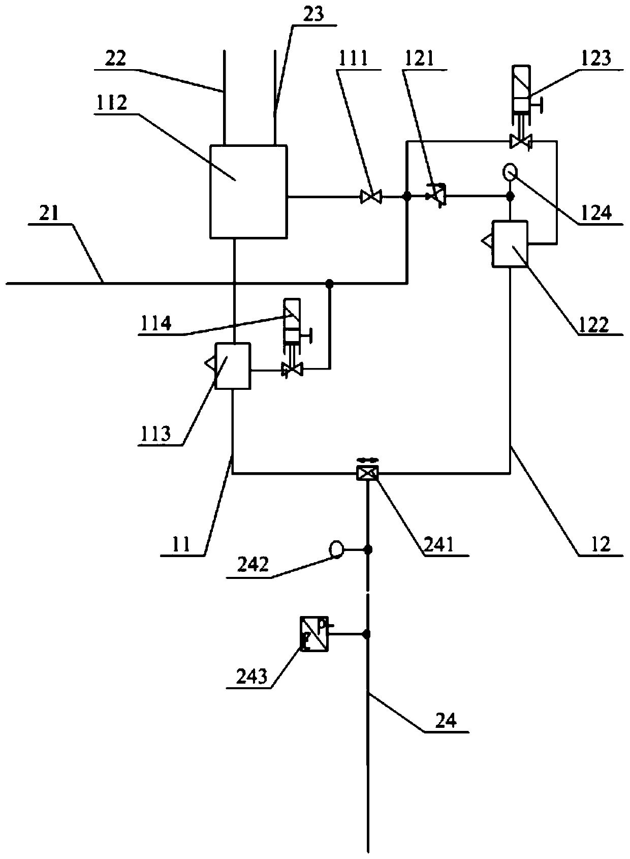
[0025] Please refer to figure 1 , figure 1 It is a schematic diagram of the cooperative structure of the rail vehicle braking system provided by a specific embodiment of the present invention.

[0026] In a specific embodiment, the rail locomotive brake system provided by the present invention includes a control module, a main air pipe 21, a train pipe 22, an action pipe 23, a comparison valve 241, a brake cylinder, and a brake cylinder connected to the c...


PUM


Abstract

The invention discloses a railway locomotive braking system which comprises a control module, a main air pipe, a train pipe, an action pipe, a comparison valve, a brake cylinder and a brake cylinder pipe communicating between the comparison valve and the brake cylinder, wherein a distribution valve passage and an emergency redundant passage are connected in parallel between the main air pipe and the comparison valve; the distribution valve passage is sequentially provided with a plug valve, a distribution valve, a first switching valve and an air-electric linkage valve in the air flow direction; the emergency redundant passage is sequentially provided with a pressure regulating valve, a second switching valve and an electromagnetic valve in the air flow direction; and the brake cylinder pipe is sequentially provided with a first test opening and an air pressure sensor in the air flow direction. The railway locomotive braking system can accurately and efficiently detect the fault of theemergency redundant passage. The invention further discloses an emergency redundant passage detection method based on the rail locomotive braking system.

Description

technical field [0001] The invention relates to the technical field of failure detection of supporting components of a rail locomotive braking system, in particular to a rail locomotive braking system. The invention also relates to an emergency redundant path detection method based on the rail locomotive braking system. Background technique [0002] In a general rail locomotive braking system, the function of the emergency redundant channel is to transmit the total air pressure limited by the pressure regulating valve to the braking system on the emergency redundant channel by triggering emergency braking when the channel of the distribution valve fails. In the cylinder pipe, it achieves the function of redundancy of the brake cylinder pipeline to ensure the stable operation of the vehicle braking system. [0003] Since the distribution valve passage and the emergency redundant passage of the existing rail locomotive braking system share the same brake cylinder sensor, when...

Claims


Application Information

Patent Timeline
Patent Type & Authority Applications(China)
IPC IPC(8): B60T17/22
CPCB60T17/228
Inventor 罗智迅刘泉乐燕飞曾春军杨智
Owner QINGDAO SRI TECH CO LTD
Why Eureka
Try Eureka