
Auxiliary beam unloading method during down-crossing high-speed railway bridge transition section

A technology for high-speed railways and transition sections, applied in bridges, bridge construction, erection/assembly of bridges, etc., can solve problems such as unfavorable pile foundations and no effective construction measures for high-speed railways, to ensure safe operation and less interference with existing structures , reduce the effect of eccentric load

Active Publication Date: 2019-07-26
TONGJI UNIV
View PDF5 Cites 0 Cited by
  • Summary
  • Abstract
  • Description
  • Claims
  • Application Information

AI Technical Summary

Problems solved by technology

[0003] Most of the existing road underpassing projects in China are box culverts and other structures passing under the operating railway, and when the box culvert and other structures pass under the bridge near the high-speed railway road-bridge transition section, the underpassing project will have a greater impact on the railway operation. It often forms unfavorable unbalanced loads for high-speed railway pile foundations
[0004] For the unloading of the partial load of the pile foundation of the high-speed railway bridge in the underpass project, there are no effective construction measures in China

Method used


Image

  • Auxiliary beam unloading method during down-crossing high-speed railway bridge transition section
  • Auxiliary beam unloading method during down-crossing high-speed railway bridge transition section
  • Auxiliary beam unloading method during down-crossing high-speed railway bridge transition section

Examples


Embodiment

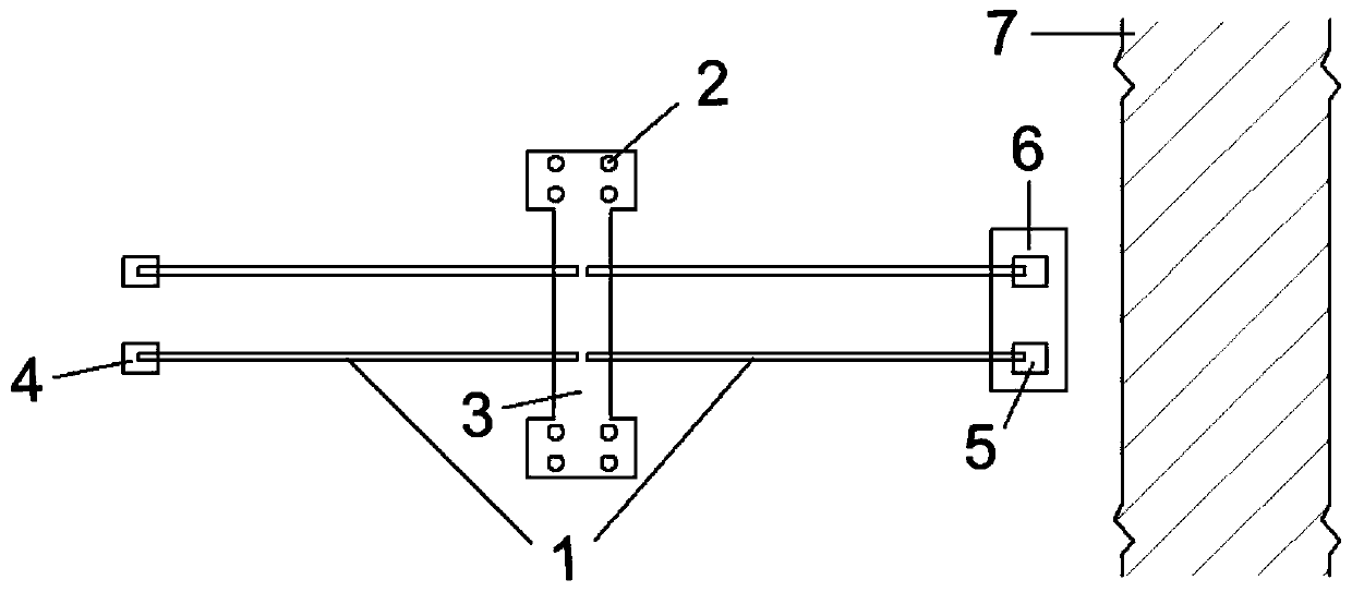
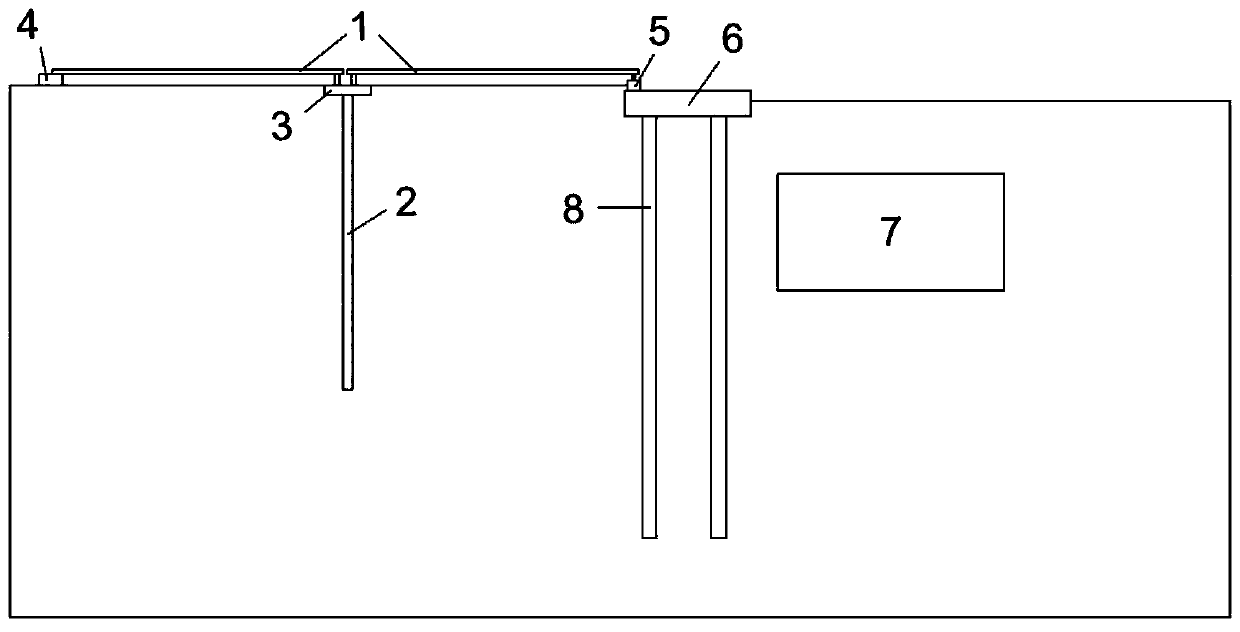
[0040] A frame bridge on the right side of a road passes under a high-speed railway bridge. The outer edge of the side wall of the box body on the south side is 13.43m away from the abutment end of the high-speed railway bridge. The box body is 40.19m long, 15.1m wide and 7.7m high. The thickness of the top plate is 0.9m, the thickness of the bottom plate is 1m, the side wall is 1.05m, and there are 3m conjoined U grooves on both sides of the box body. In order to control the horizontal deformation of the abutment during the construction process of the underpass of the road frame bridge, improve the longitudinal stability of the line, and ensure the safe operation of the high-speed railway, the technical solution provided by this application is used for processing in the underpass section. figure 1 and figure 2 They are the plan and elevation schematic diagrams of the application scenarios of this application, respectively.

[0041] A method for unloading a convenient beam w...


PUM


Abstract

The invention belongs to the technical field of railway engineering construction and maintenance, and provides an auxiliary beam unloading method when down-crossing a high-speed railway bridge transition section. The method that auxiliary beams are erected on the side, away from a down-crossing structure, of a high-speed railway bridge abutment is adopted, and thus the longitudinal stability of the high-speed railway bridge abutment is improved. According to implement of the auxiliary beams, uniform load acting on a roadbed is transformed into focus force acting on the high-speed railway bridge pile foundation and a drilling grouting pile, thus additional lateral force subjected to the high-speed railway bridge pile foundation is reduced, and the action of unloading is achieved. Accordingto implement of an auxiliary beam pile foundation, loading from the upper part auxiliary beams is passed into deep in foundation soil, the unbalance loading action introduced by train load is reduced,thus the influence on the high-speed railway bridge abutment of down-crossing construction is reduced. According to the auxiliary beam unloading method when down-crossing the high-speed railway bridge transition section, unbalance loading introduced by the train load behind the bridge abutment is reduced, the vertical load of a high-speed railway bridge beam is also increased, the two aspects areboth advantageous to the horizontal deformation of the abutment, the construction speed is high, and safety and stability of the high-speed railway during down-crossing construction are guaranteed.

Description

technical field [0001] The application relates to the technical field of railway engineering construction and maintenance, in particular to a method for unloading a convenient beam when passing under a high-speed railway bridge transition section. Background technique [0002] In recent years, with the continuous development of roads and other infrastructure in our country, road engineering inevitably encounters more and more construction problems in construction projects, especially the cross-construction of roads and high-speed railways. The security and stability of the country and the construction of road engineering have brought new threats and challenges. [0003] Most of the existing road underpassing projects in China are box culverts and other structures passing under the operating railway, and when the box culvert and other structures pass under the bridge near the high-speed railway road-bridge transition section, the underpassing project will have a greater impac...

Claims


Application Information

Patent Timeline
Patent Type & Authority Applications(China)
IPC IPC(8): E01D21/00
CPCE01D21/00
Inventor 周顺华狄宏规郭慧吉黄道刚宋福贵吴挺
Owner TONGJI UNIV
Learn More