
Identification method of single-phase ground fault point in non-effectively grounded distribution network

A single-phase grounding fault, non-effective grounding technology, applied in the electrical field, can solve the problems of inability to determine the exact location of the fault, many fault branches, and high signal sampling frequency

Active Publication Date: 2021-02-26
SICHUAN UNIV
View PDF5 Cites 0 Cited by
  • Summary
  • Abstract
  • Description
  • Claims
  • Application Information

AI Technical Summary

Problems solved by technology

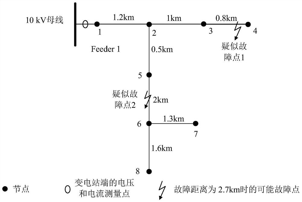
However, since the distribution network structure is usually radial, such as figure 1 As shown, when the fault distance is determined, the possible fault points are located on multiple branches, and the exact location of the fault cannot be determined only based on the fault distance
[0004] At present, there are mainly two identification methods for distribution network fault branches. The fault branch identification based on traveling wave reflection spectrum analysis has the disadvantage of requiring high sampling frequency of signals, requiring MHz level, and there are many fault branches, and traveling wave non-refractive reflection is complicated. , it is difficult to identify the frequency spectrum; another method is the branch identification method based on the fault detector, which requires a large number of measuring devices, and the installation and operation cost of the measuring devices is relatively high

Method used


Image

  • Identification method of single-phase ground fault point in non-effectively grounded distribution network
  • Identification method of single-phase ground fault point in non-effectively grounded distribution network
  • Identification method of single-phase ground fault point in non-effectively grounded distribution network

Examples


Embodiment Construction

[0027] The specific embodiments of the present invention will be described in detail below in conjunction with the accompanying drawings, so that those skilled in the art can understand the present invention. However, it should be clear that the embodiments described below are only some, not all, embodiments of the present invention. Without departing from the spirit and scope of the present invention defined and determined by the appended claims, all other embodiments obtained by persons of ordinary skill in the art without any creative work belong to the protection scope of the present invention.

[0028] This scheme provides a method for identifying single-phase ground fault points in non-effectively grounded distribution networks, which includes:

[0029] S1. Determine all suspected fault points of the single-phase ground fault according to the topological structure of the non-effectively grounded distribution network;

[0030] S2. Calculate the fault phase voltage V of t...


PUM


Abstract

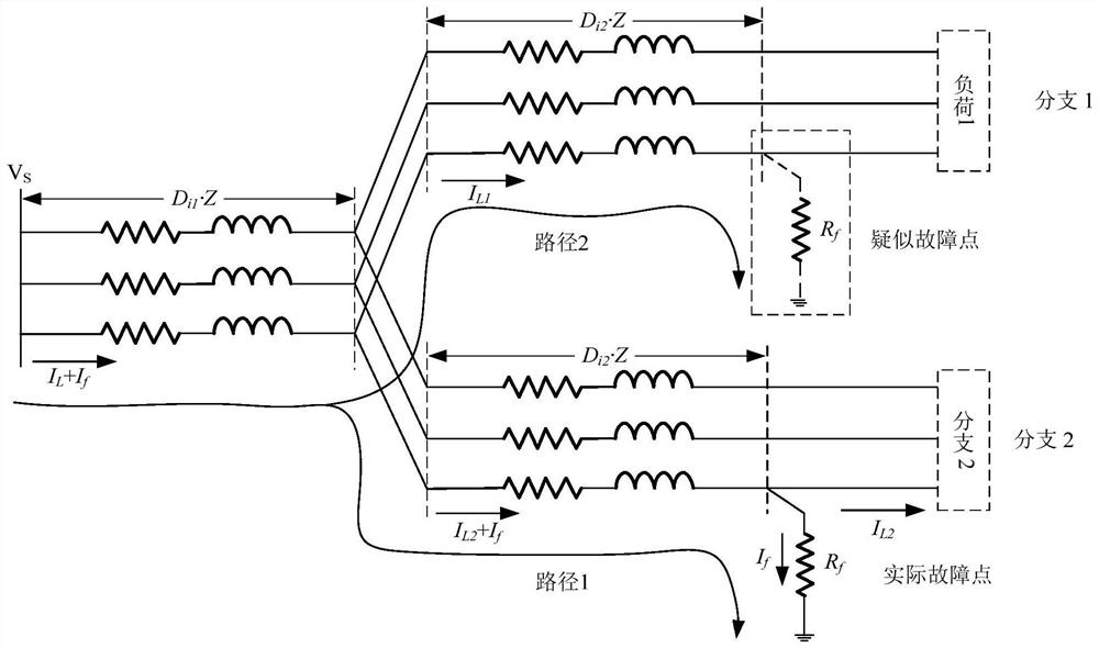
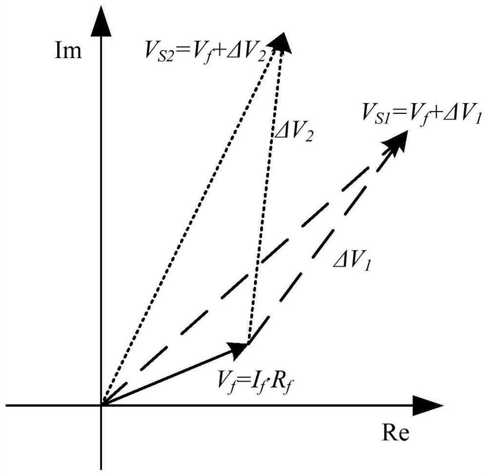
The invention discloses a single-phase grounding fault point identification method of an ineffectively grounded distribution network, which belongs to the electrical field. The identification method includes: determining all suspected fault points of the single-phase ground fault according to the topological structure of the non-effectively grounded distribution network; calculating the fault phase voltage V of the substation end busbar of each suspected fault point Si :V Si =(I L +I f )·D i1 ·Z+(I i +I f )D i2 ·Z+I f · R f , among them, I L is the total load current of the feeder fault phase before the actual measurement, I f is the fault current, I i is the fault phase load current of the branch where the suspected fault point is located, D i1 is the distance between the busbar at the substation end and the node of the branch where the suspected fault point is located, D i2 is the distance between the suspected fault point and the node, i=(1, 2, ..., n), n is the total number of suspected fault points, Z is the line unit impedance, R f is the fault resistance; calculate each fault phase voltage V Si Compared with the measured fault phase voltage V of the substation terminal busbar S The proximity between F i , all proximity F i The suspected fault point corresponding to the maximum value in is the actual fault point.

Description

technical field [0001] The invention relates to the electrical field, in particular to a method for identifying a single-phase ground fault point in a non-effectively grounded distribution network. Background technique [0002] The single-phase-to-ground fault in the non-effectively grounded distribution network is the main fault type of the distribution network. After a single-phase ground fault occurs in the non-effectively grounded system, the load can continue to run for 2 hours without being affected. [0003] After a single-phase ground fault, quickly determining the single-phase ground fault point is of great significance for timely troubleshooting and restoration of system power supply. However, since the distribution network structure is usually radial, such as figure 1 As shown, when the fault distance is determined, the possible fault points are located on multiple branches, and the exact location of the fault cannot be determined only based on the fault distanc...

Claims


Application Information

Patent Timeline
Patent Type & Authority Patents(China)
IPC IPC(8): G01R31/08
CPCG01R31/086
Inventor 张文海肖先勇郑子萱王杨
Owner SICHUAN UNIV
Learn More