Laser radar

A laser radar and laser technology, applied in the field of radar, can solve the problems of complex laser collimation structure, achieve the effect of small laser collimation, reduce space, and simplify the laser collimation structure

Pending Publication Date: 2019-07-26
SHENZHEN LITRA TECH
View PDF0 Cites 3 Cited by
  • Summary
  • Abstract
  • Description
  • Claims
  • Application Information

AI Technical Summary

Problems solved by technology

[0003] The purpose of the present invention is to introduce a laser radar to solve the technical problems in the prior art that the laser collimation structure is complex and it is difficult to arrange a collimation structure with better collimation effect in a limited space

Method used


Image

  • Laser radar
  • Laser radar
  • Laser radar

Examples


Embodiment Construction

[0027] In order to make the technical problems, technical solutions and beneficial effects to be solved by the present invention clearer, the present invention will be further described in detail below in conjunction with the accompanying drawings and embodiments. It should be understood that the specific embodiments described here are only used to explain the present invention, not to limit the present invention.

[0028] It should be noted that when an element is referred to as being “fixed” or “disposed on” another element, it may be directly on the other element or be indirectly on the other element. When an element is referred to as being "connected to" another element, it can be directly connected to the other element or indirectly connected to the other element.

[0029] It is to be understood that the terms "length", "width", "top", "bottom", "front", "rear", "left", "right", "vertical", "horizontal", "top" , "bottom", "inner", "outer" and other indicated orientations...


PUM


Abstract

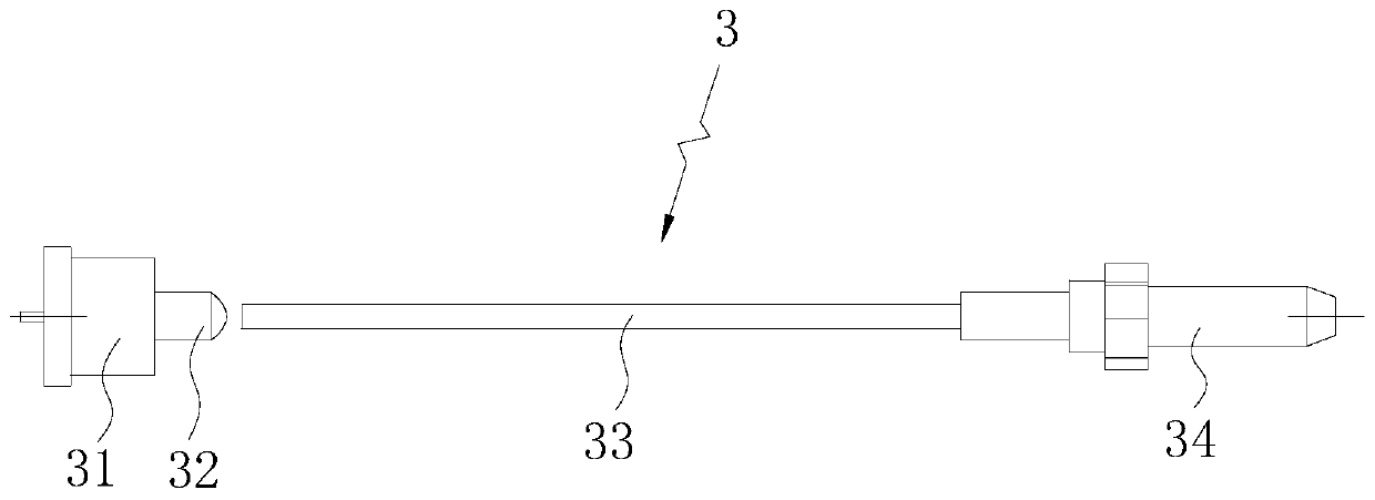
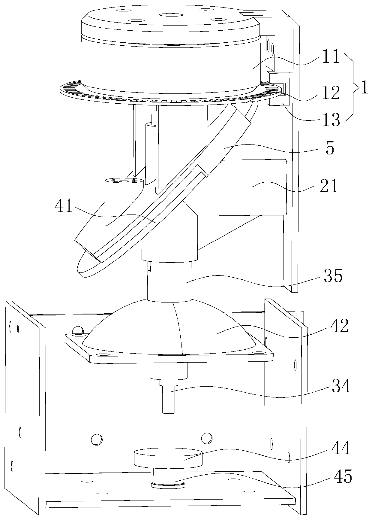
The invention provides a laser radar which comprises an optical fiber collimation structure, a laser emission structure, a laser receiving structure and a driving assembly. The optical fiber collimation structure comprises a laser source used for emitting laser; an optical fiber having flexibility and used for transmitting laser light; a laser coupling lens, two ends of which are respectively connected with the laser source and the optical fiber; and a collimating lens, which is arranged at the light outlet end of the optical fiber, and the light outlet end of the optical fiber and the collimating lens are coaxially arranged. According to the laser radar of the invention, laser emitted by the optical fiber is in a circular spot shape, the divergence angle is small, the laser is more easilycollimated by the collimating lens, the laser collimating structure is simplified, and the optical fiber is flexible and bendable, so that the laser source and the collimating lens are not required to be coaxially arranged, the space inside the laser radar can be fully utilized, and a good laser collimating effect can be achieved in a limited space.

Description

technical field [0001] The invention belongs to the technical field of radar, and more specifically relates to a laser radar. Background technique [0002] Lidar has excellent performance in map construction, obstacle avoidance, ranging and other fields, and is widely used in robots, AGV (logistics handling), unmanned driving and other industries. At present, most of the pulsed TOF (time-of-flight ranging) ranging lidars produced by domestic and foreign lidar companies use parallel axis and coaxial structures. In the coaxial laser radar, when the divergence of the laser source is large, the structure of the laser collimation is complicated, which makes it difficult to do a good job of laser collimation in a limited space, and the design of the laser collimation structure is difficult. Contents of the invention [0003] The purpose of the present invention is to introduce a laser radar to solve the technical problems in the prior art that the laser collimation structure is...

Claims


Application Information

Patent Timeline
Patent Type & Authority Applications(China)
IPC IPC(8): G01S17/08G01S7/481
CPCG01S7/4812G01S7/4818G01S17/08
Inventor 吴康达张忠祥周伟健林小睿
Owner SHENZHEN LITRA TECH
Why Eureka
Try Eureka