Arc-shaped light box

An arc, light box technology, applied in the direction of instruments, display devices, illuminated signs, etc., can solve the problems of inconvenient installation, short service cycle, thick thickness, etc., achieve smooth transition of arc, easy to manufacture and install, and meet outdoor applied effect

Inactive Publication Date: 2019-07-26
湖南凯星电子科技有限公司
View PDF0 Cites 1 Cited by
  • Summary
  • Abstract
  • Description
  • Claims
  • Application Information

AI Technical Summary

Problems solved by technology

There are also defects in the following aspects when using the direct-down backlight of this simple box structure to make light box display equipment: First, the box is surrounded by solid and opaque box walls, and there are serious problems after splicing into a light box with a large area of ​​light. dark frame
The second is that the thickness is too thick and the installation is inconvenient; although the method of installing a light diffusion plate on the opening surface can improve the uniformity of the emitted light and reduce the thickness of the cabinet, but the cabinet walls around the cabinet cannot achieve shadowless splicing The third is that due to the limited specifications of the finished material of the light-transmitting board or light-diffusing board (usually 1.22m×2.44m), the light box made into a larger size can only be directly covered with the light box cloth on the opening surface (called " Rab Light Box"), for the "Rab Light Box" that emits light in a large area, the light box cloth will fluctuate with the wind, which not only affects the appearance, but also is easy to be damaged and has a short service life; once the light box cloth is damaged, it will bring many inconveniences. safety factor
[0008] From the above, it can be seen that it is difficult to perform shadowless splicing of backlight in the prior art, resulting in the lack of large-area light-emitting backlight display devices on the market, especially large-area arc-shaped backlight display devices.

Method used


Image

  • Arc-shaped light box
  • Arc-shaped light box
  • Arc-shaped light box

Examples


Embodiment approach

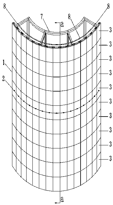
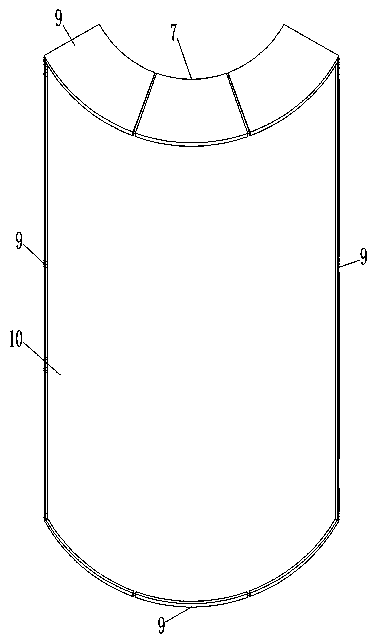
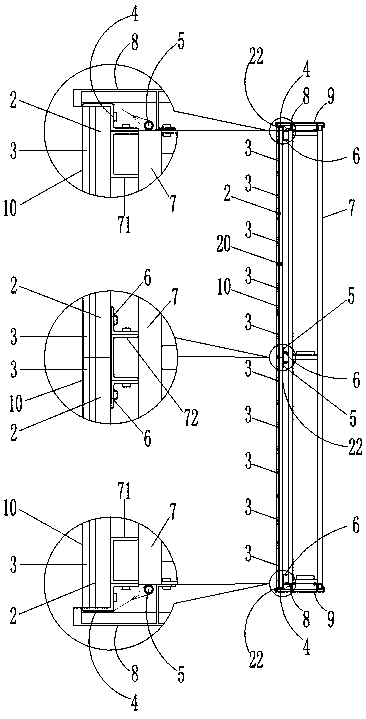
[0057] An embodiment of a curved light box of the present invention, such as Figure 1 to Figure 3 As shown, the curved light box includes: a curved light emitting wall 1, a light-transmitting screen 10 covering and installed in front of the curved light emitting wall 1; the curved light emitting wall 1 is composed of N long strip light emitting units The arc-shaped positioning beam 6 is fixedly installed on the structure 7 (such as steel structures, walls and other structures), and the surrounding parts of the arc-shaped luminous wall 1 are provided with hanging rods 8 (such as round pipes, round steel, square steel pipes, angle steel, etc.) piece), the light-transmitting picture 10 is connected with the picture-hanging rod 8 through a pendant or a cable tie or a steel wire; The elongated light emitting unit 2 is composed of an elongated supporting shell 20 and light emitting modules 3 arranged in a straight line at the front of the elongated supporting shell 20 . Its light-...


PUM


Abstract

The invention relates to an arc-shaped light box. The arc-shaped light box comprises an arc-shaped light-emitting wall and a light-admitting picture in front of the arc-shaped light-emitting wall; thearc-shaped light-emitting wall is composed of N long-strip-shaped light-emitting units; each long-strip-shaped light-emitting unit is composed of a long-strip-shaped supporting shell and a light-emitting module located at the front portion of the long-strip-shaped supporting shell; each light-emitting module comprises a light diffusion module composed of a plurality of cone bodies in display, light source panels and screw base columns of the two rows of light-emitting modules at the rear side and close to the edge; each light source panel is arranged at the rear side of the corresponding light diffusion module, so that a light source light-emitting face tightly fits the top face of the corresponding cone body, thereby emitting uniform light on a light diffusion module panel; each long-strip-shaped supporting shell is a profile integrally formed by a bottom plate on the corresponding supporting shell and a connecting mechanism on the corresponding supporting shell; and a middle area isprovided with an opening in the bottom plate of each supporting shell; a power supply terminal of the rear side is placed in the opened area of the bottom plate of the corresponding supporting shell.According to the technical scheme, the long-strip-shaped light-emitting units can not only be spliced into a large-area light-emitting light box display device, but also meet the splicing requirements of an arc-shaped structure.

Description

technical field [0001] The invention relates to the field of light boxes, in particular to an arc light box. Background technique [0002] As we all know, light boxes have a wide range of applications. It involves construction fields (such as: showcases, lighting roofs, lighting walls, signage, emergency lights, etc.), industrial fields (such as: film viewers, light diffusion module panels for instruments and meters) , machine identification, production line process instructions, metering equipment, etc.), lighting fields (such as: flat panel lights, light curtains, light walls, floor lights, etc.), civil fields (such as: photo frames, decorative paintings, dressing tables, etc.), commercial fields (such as: item array cabinets, guide signs, identification signs, etc.), medical fields (such as: X-ray light emitters, vision detectors, incubators, test kits, constant temperature covers, operation cabinets, etc.), advertising communication fields (such as : Light box advertise...

Claims


Application Information

Patent Timeline
Patent Type & Authority Applications(China)
IPC IPC(8): G09F13/04
CPCG09F13/0413G09F13/0418
Inventor 罗言超姚淑英
Owner 湖南凯星电子科技有限公司
Why Eureka
Try Eureka