
Railway coverage method, wide-beam high-gain antenna and multi-band common antenna

A railway and antenna technology, applied in the directions of antenna, antenna grounding device, antenna support/installation device, etc., can solve the problems of shortening the coverage distance of a single station, tipping of communication towers, affecting the safety of railway operation, etc., to solve the problem of discontinuous coverage. , The effect of saving the investment cost of site construction and reducing the density of site layout

Pending Publication Date: 2019-07-26
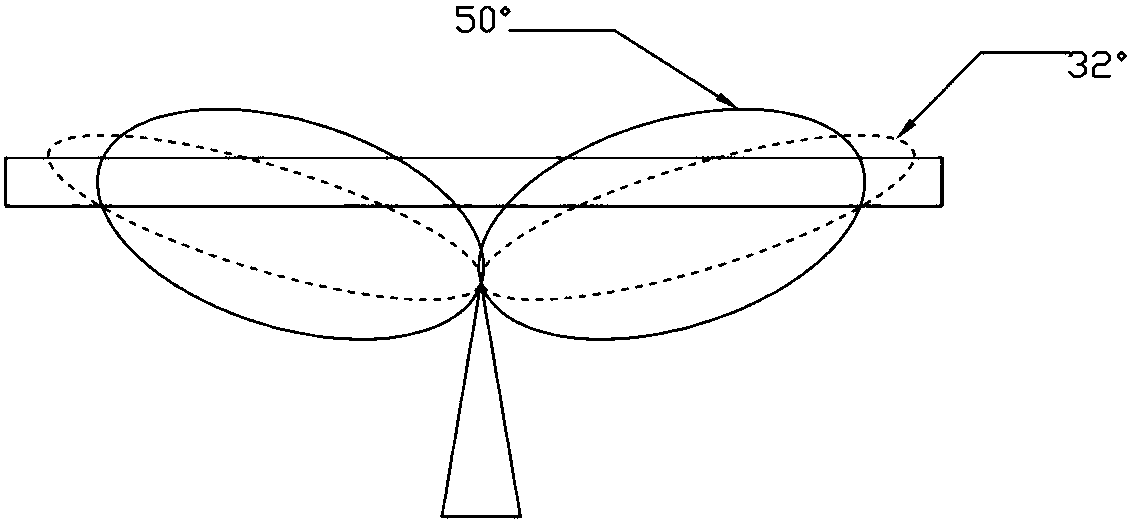
CHINA UNITED NETWORK COMM GRP CO LTD +1
View PDF6 Cites 1 Cited by
  • Summary
  • Abstract
  • Description
  • Claims
  • Application Information

AI Technical Summary

Problems solved by technology

[0003] However, due to site acquisition or safety issues in some scenarios, some sites of the operator cannot keep a relatively close distance from the railway line. For special reasons, the toppling of the communication tower will directly affect the safety of the railway operation, especially after the accident of the communication tower collapsing and scratching the railway in a certain place, the railway company requires that the new site must keep a certain safe distance from the railway track (such as station rail distance is greater than 20 meters), but at this distance, the radiation direction of the main lobe of the antenna will form a certain angle with the rail, resulting in weak coverage or blind coverage in the horizontal angle area between the two sectors, such as figure 2 Shown:
[0004] Therefore, the use of general narrow-beam high-gain antennas (horizontal plane width 32°, gain 18dBi (≤1GHz) or 20dBi (≥1.4GHz)) antennas cannot effectively solve the problem of discontinuous communication signal coverage along the railway. Further, if only using Conventional antennas with a half-power beamwidth of 65° horizontal plane (such as 18dBi, 1.8GHz) will shorten the coverage distance of a single station due to the small gain, increase the switching frequency when the train is moving fast, and increase the call drop rate, which will affect the user experience. ; At the same time, it leads to more densely built stations and higher construction costs

Method used


Image

  • Railway coverage method, wide-beam high-gain antenna and multi-band common antenna
  • Railway coverage method, wide-beam high-gain antenna and multi-band common antenna
  • Railway coverage method, wide-beam high-gain antenna and multi-band common antenna

Examples


Embodiment Construction

[0020] In order to make the object, technical solution and advantages of the present invention clearer, the present invention will be further described in detail below in conjunction with the accompanying drawings and specific implementation methods. It should be understood that the specific embodiments described here are only used to explain the present invention, and do not limit the protection scope of the present invention.

[0021] Unless otherwise defined, all technical and scientific terms used herein have the same meaning as commonly understood by one of ordinary skill in the technical field of the invention. The terminology used herein in the description of the present invention is only for the purpose of describing specific embodiments, and is not intended to limit the present invention. As used herein, the term "and / or" includes any and all combinations of one or more of the associated listed items.

[0022] The "first", "second", and "third" mentioned in the prese...


PUM


Abstract

The first purpose of the invention is to provide an along-the-railway communication coverage method, which can realize antenna signal coverage in narrow and narrow scenes. The second purpose of the invention is to provide a wide-beam high-gain antenna, which can realize that the width of a half-power beam in a horizontal plane is about 65 degrees and the gain of the antenna is larger than or equalto 19 dBi. The third purpose of the invention is to provide a wide-beam high-gain multi-band common antenna, which can realize that the width of the half-power beam in the horizontal plane is about 65 degrees, the gain of the antenna at the low frequency band (less than or equal to 1 GHz) is greater than or equal to 16 dBi, and the gain of the antenna at the high frequency band (greater than or equal to 1.4 GHz) is greater than or equal to 19 dBi. Further, for reducing the difficulty of adjusting an electrical downward inclination angle in an engineering use process and avoiding the coverageof "shadow under a tower", a vertical plane of the antenna needs to be subjected to shape design of "null filling" and "vertical plane 3dB beam width increment"; and furthermore, for reducing the bearing requirements on a lifting pole and improving an engineering safety coefficient, the antenna is required to have a miniaturization characteristic, for example, the width of the antenna is less thanor equal to 400 mm.

Description

technical field [0001] The invention relates to the technical field of mobile communication equipment, in particular to a railway coverage method, a wide-beam high-gain antenna and a multi-band shared antenna. Background technique [0002] At present, for narrow and long area scenarios such as railways, narrow-beam high-gain antennas (horizontal plane width 32°, gain 18dBi (≤1GHz) or 20dBi (≥1.4GHz)) are generally used for coverage to increase the coverage distance of a single station as much as possible and reduce Switch frequency when the train is moving fast, and achieve continuous and uniform coverage in the sector. If the site is close to the railway line (such as less than 10 meters), it is a better solution to use two pairs of narrow-beam high-gain antennas for back-to-back coverage on both sides of the track, such as figure 1 Shown: [0003] However, due to site acquisition or safety issues in some scenarios, some sites of the operator cannot keep a relatively clos...

Claims


Application Information

Patent Timeline
Patent Type & Authority Applications(China)
IPC IPC(8): H01Q1/12H01Q1/36H01Q1/48H01Q15/14H01Q1/32
CPCH01Q1/12H01Q1/36H01Q1/48H01Q15/14H01Q1/32
Inventor 王波邱涛孙善球林学进栾帅黄立文刘小权
Owner CHINA UNITED NETWORK COMM GRP CO LTD
Learn More