Efficient heat dissipation intelligent controller based on physical transmission and flow speed control

An intelligent controller and controller technology, which is applied in the direction of modification, cooling/ventilation/heating transformation, electrical components, etc. by conduction and heat transfer. It can increase the heat transmission rate, increase the transfer medium, and reduce the internal energy.

Active Publication Date: 2019-07-26
绍兴市亚索新能源科技有限公司
View PDF4 Cites 0 Cited by
  • Summary
  • Abstract
  • Description
  • Claims
  • Application Information

AI Technical Summary

Problems solved by technology

[0005] Aiming at the deficiencies in the prior art, the purpose of the present invention is to provide an efficient heat dissipation intelligent controller that uses physical transfer to match the flow rate, so as to solve the problem of cooling treatment by using simple physical transfer. The transfer of heat between the metal sheet and the heat sink is used to cool down. First, the energy transfer between the metal sheet and the heat sink is too simple, the energy transfer medium is too small, and the heat consumption effect is low; second, only the physical medium is used for transfer. It cannot cool down quickly, and at the same time, the metal sheet and heat sink are large in size, and the internal energy is not easy to consume, and it is easy to collect heat and heat up, causing the overall temperature rise of the intelligent controller

Method used


Image

  • Efficient heat dissipation intelligent controller based on physical transmission and flow speed control
  • Efficient heat dissipation intelligent controller based on physical transmission and flow speed control
  • Efficient heat dissipation intelligent controller based on physical transmission and flow speed control

Examples


Embodiment Construction

[0027] In order to make the technical means, creative features, goals and effects achieved by the present invention easy to understand, the present invention will be further described below in conjunction with specific embodiments.

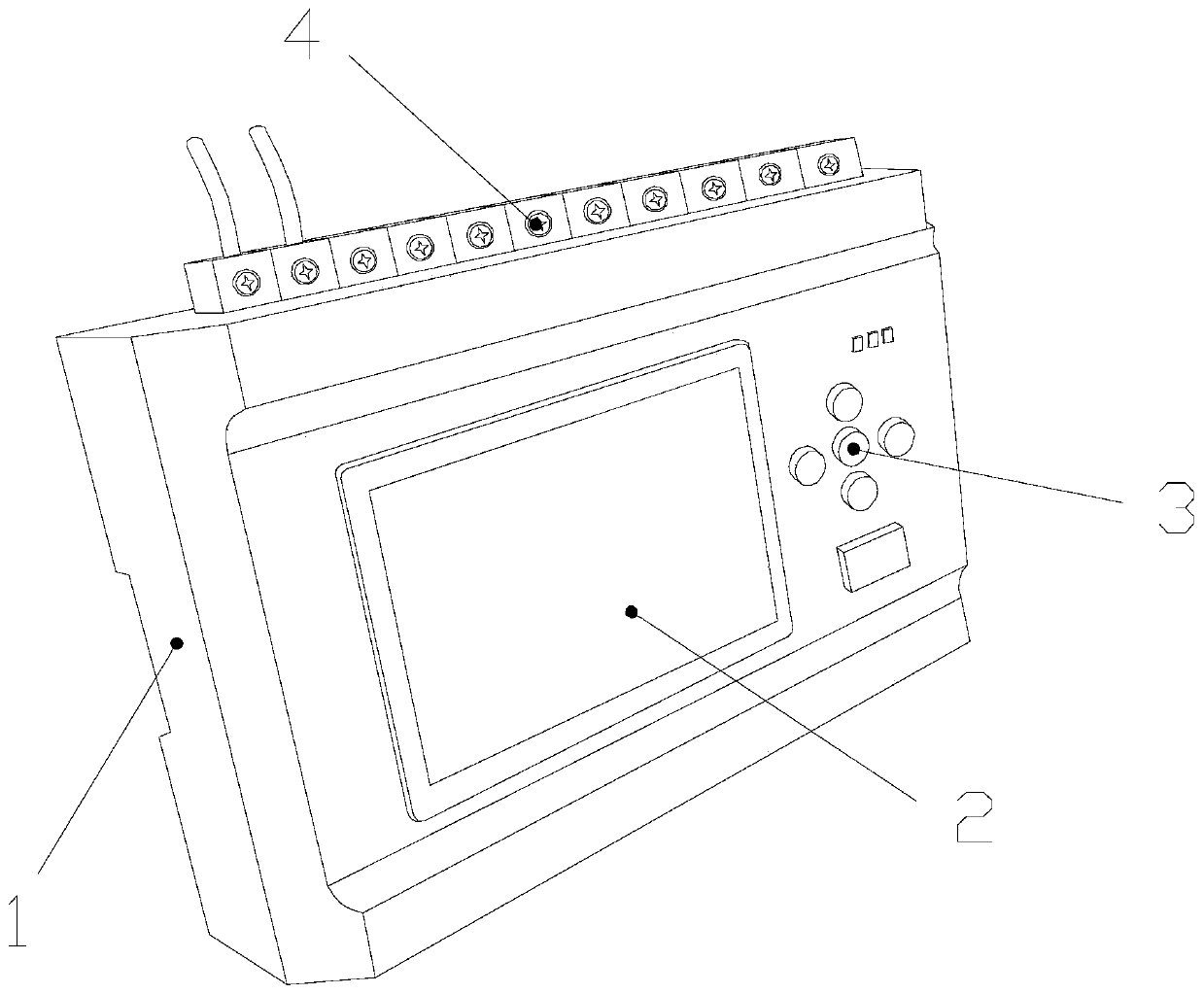
[0028] see figure 1, the present invention provides a high-efficiency heat-dissipating intelligent controller technical solution using physical transmission to match the flow rate: its structure includes a controller core device 1, a display 2, buttons 3, and a connecting seat 4. The front end of the controller core device 1 is connected to the display 2 The rear end is connected by a card slot, the inside of the display 2 is electrically connected to the inside of the controller core device 1, the inside of the controller core device 1 is embedded with the bottom of the connecting seat 4, and the middle end of the connecting seat 4 is connected to the control The top of the controller core device 1 is fixedly connected by screws, the rear end of...


PUM


Abstract

The invention discloses an efficient heat dissipation intelligent controller based on physical transmission and flow speed control. The efficient heat dissipation intelligent controller structurally comprises a controller inner core device, a display, keys and a connecting base; the middle of a supporting rod is of a relatively thin straight rod structure, so that a relatively large gap is formedbetween the two ends of the middle end of the supporting rod, the heat dissipation effect is improved, the heat energy consumption in the transferring process is realized, and the internal energy is further reduced; the two ends of a transmission inner rod are connected with a transmission rod, so that heat transfer is achieved, the transmission medium is increased, and heat is further consumed inthe transmission process; the top of an air pipe is attached to a water tank, and fan blades achieve indirect cooling by increasing the air speed, so that the surface temperature is reduced under theflowing wind power of the transmission rod, the flow speed is increased by pushing the water flow through a pump machine, the flowing water is utilized to continuously take away heat energy, and thefinal cooling treatment is realized; and the cooling effect is improved by means of physical transmission and air flow cooling, so that the controller is prevented from being heated and expanded due to a too low cooling effect, and the overall temperature rising of the controller is avoided.

Description

technical field [0001] The invention is an efficient heat dissipation intelligent controller utilizing physical transmission to match flow velocity, and belongs to the field of intelligent controllers. Background technique [0002] Due to the popularity of electrical appliances, many different types of mechanical products are now integrated into our lives. At this time, intelligent controllers are generally used to control different electrical appliances in a unified manner. Therefore, the sensor has a large operating burden and is prone to generate heat. Due to the long-term operation of some electrical appliances, the controller will continue to heat up along with the work. A certain cooling device is required to ensure the long-term stable operation of the intelligent controller. [0003] However, the existing intelligent controller has the following disadvantages: [0004] In terms of cooling treatment, a simple physical transfer method is generally used for cooling tre...

Claims


Application Information

Patent Timeline
Patent Type & Authority Applications(China)
IPC IPC(8): H05K7/20
CPCH05K7/20136H05K7/20218H05K7/20272H05K7/2039
Inventor 黄劻湛
Owner 绍兴市亚索新能源科技有限公司
Why Eureka
Try Eureka