Fuel injection pumps, fuel injection devices, internal combustion engines

A fuel injection pump and fuel injection valve technology, which is applied to fuel injection devices, fuel injection pumps, charging systems, etc., can solve problems such as poor plunger action and bite, and achieve the effect of suppressing poor action.

Active Publication Date: 2021-05-14
MITSUBISHI HEAVY IND LTD +1
8 Cites 0 Cited by

AI-Extracted Technical Summary

Problems solved by technology

At this time, if lubricating oil adheres to the outer peripheral surface of the plunger, the adhering lubricat...

Method used

[0073] In the fuel injection pump according to the present embodiment, the spring receiving member 52 is fixed to the plunger 23, and the return spring 51 is stretched between the pump housing 21 and the spring receiving member 52, whereby the plunger 23 The fuel compression chamber 65 is biased and supported, and the lubricating oil reservoir 91 is provided closer to the fuel compression chamber 65 side than the fixed position of the spring receiving member 52 . Therefore, by providing the lubricating oil reservoir 91 in the range from the fixed position of the spring receiving member 52 to the fuel compression chamber 65 side, the discharge property of the lubricating oil entering the lubricating oil reservoir 91 can be maintained. Furthermore, by forming the lubricating oil reservoir 91 long in the axial direction, even if the lubricating oil sticks when the lift force of the plunger is small at low load, it can be stored in the lubricating oil reservoir 91, and Suppresses the occurrence of plunger malfunction.
[0074] In the fuel injection pump according to this embodiment, the plunger 23 is fixed so as to pass through the spring receiving member 52, and the lubricating oil reservoir 91 is provided closer to the position where the plunger 23 is exposed from the spring receiving member 52. Fuel compression chamber 65 side. Therefore, by limiting the formation area of ​​the lubricating oil reservoir 91 , it is possible to reduce the points of change of peripheral components and suppress an increase in cost.
[0075] In the fuel injection pump of the present embodiment, the lubricating oil reservoir 91 is constituted by a small-diameter portion 92 (97) having a smaller diameter than the small-diameter portion 47. Therefore, the roughness of the lubricating oil reservoir portion serving as the non-sliding portion can be reduced, and the processing cost can...

Abstract

In a fuel injection pump, a fuel injection device, and an internal combustion engine, a pump casing (21), a plunger barrel (22) arranged in the pump casing (21), and a plunger barrel (22) supported freely in the axial direction are provided. The plunger (23) in 22), the lubricating oil supply passage (81) that supplies lubricating oil (fuel) between the plunger barrel (22) and the plunger (23), and the plunger (23) that is concavely arranged ) in the lubricating oil reservoirs (91, 96) at positions exposed from the plunger barrel (22).

Application Domain

Machines/enginesFuel injecting pumps

Technology Topic

Injection pumpOil supply +4

Image

  • Fuel injection pumps, fuel injection devices, internal combustion engines
  • Fuel injection pumps, fuel injection devices, internal combustion engines
  • Fuel injection pumps, fuel injection devices, internal combustion engines

Examples

  • Experimental program(1)

Example Embodiment

[0036] Preferred embodiments of a fuel injection pump, a fuel injection device, and an internal combustion engine according to the present invention will be described in detail below with reference to the drawings. In addition, this embodiment does not limit this invention, and when there are several embodiments, the embodiment which combined each embodiment is also included.
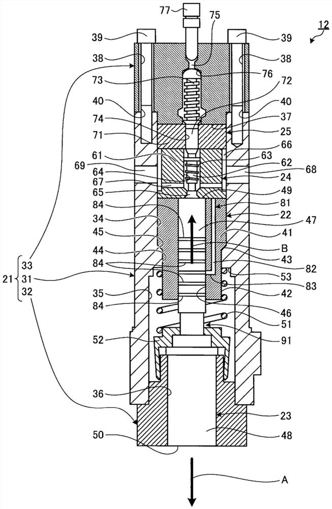
[0037] Image 6 is a schematic configuration diagram showing a fuel injection device according to the present embodiment.
[0038] In this embodiment, if Image 6 As shown, the fuel injection device 10 is mounted on a large marine diesel engine (internal combustion engine) mounted on a ship. The fuel injection device 10 includes a fuel injection valve 11 , a fuel injection pump 12 , and an accumulation control valve block 13 .
[0039] The fuel injection valve 11 injects fuel (C heavy oil) into a combustion chamber of a diesel engine (not shown). A fuel injection pump 12 pressure-feeds fuel to the fuel injection valve 11 and is connected via a fuel pipe 14 . The pressure accumulation control valve block 13 controls the drive of the fuel injection pump 12 and is installed on the side of the cylinder block of the diesel engine.
[0040] Hereinafter, the fuel injection pump 12 of the present embodiment will be described in detail. figure 1 is a schematic cross-sectional view showing the fuel injection pump of the present embodiment, figure 2 is a cross-sectional view showing a main part of the fuel injection pump according to the present embodiment, image 3 is a sectional view showing a full stroke state of a plunger in a fuel injection pump, Figure 4 is a sectional view showing the operating state of the fuel injection pump.
[0041] The fuel injection pump 12 of this embodiment, such as figure 1 As shown, a pump housing 21 , a plunger cylinder 22 , a plunger 23 , a suction valve 24 , and a discharge valve 25 are provided. Further, the plunger cylinder 22 , the suction valve 24 and the discharge valve 25 are linearly arranged in series in the longitudinal direction in the pump housing 21 , and the outer wall surface is supported by the inner wall surface of the pump housing 21 .
[0042]The pump housing 21 includes a cylindrical housing main body 31 , a cylindrical housing mount 32 , and a cylindrical pressing member 33 . The case main body 31 is provided with a first housing portion 34 for housing most of the plunger barrel 22 , the suction valve 24 and the discharge valve 25 and the like, and a second housing portion 35 for housing the plunger. Se 23 et al. The first housing portion 34 and the second housing portion 35 are formed by a continuous space portion, the first housing portion 34 is located above the second housing portion 35, and the inner diameter of the second housing portion 35 is set to be larger than that of the first housing portion 34. Large inner diameter.
[0043] The case mounting table 32 fits the outer peripheral surface of the upper end portion and the inner peripheral surface of the lower end portion (second housing portion 35 ) of the case main body 31 and connects them with fastening bolts (not shown). A support hole 36 for supporting the support plunger 23 in an axially movable manner is formed in the center portion of the case mount 32 in the radial direction. Moreover, the lower end portion of the case mounting table 32 is fixed to the pressure accumulation control valve block 13 (refer to Image 6 ) on the upper face.
[0044] The outer peripheral surface of the lower end portion of the pressing member 33 is fitted and fixed to the inner peripheral surface of the upper end portion (the first housing portion 34 ) of the case main body 31 . The outer diameter of the pressing member 33 is the same as that of the housing main body 31, and is provided with a fitting portion 37 fitted with the upper end of the first housing portion 34 in the housing main body 31 to press the discharge valve 25, Further, a plurality of axial mounting holes 38 are formed at predetermined intervals in the circumferential direction on the outer peripheral surface side. In addition, the pressing member 33 passes a plurality of fastening bolts 39 through each mounting hole in a state where the fitting portion 37 fits into the first receiving portion 34 of the case body 31 and is in close contact with the upper end surface of the case body 31 . 38 and screwed with the threaded hole 40 formed on the housing main body 31 to be fixed on the housing main body 31 .
[0045] The plunger cylinder 22 is arranged in the housing main body 31 of the pump housing 21 . The plunger barrel 22 is provided with a large-diameter portion 41 on the upper side and a small-diameter portion 42 on the lower side, and a gap is formed between the large-diameter portion 41 and the small-diameter portion 42 so that the outer peripheral surface of the large-diameter portion 41 and the outer peripheral surface of the small-diameter portion 42 are continuous. The inclined surface 43. On the other hand, the pump housing 21 is provided with a protruding portion (stopper portion) 44 protruding toward the center portion side in the radial direction on the inner peripheral surface of the first housing portion 34 . The protruding portion 44 has a ring shape, and an inclined surface 45 is formed on the upper portion. The inclined surface 45 of the protruding portion 44 is set at the same angle as the inclined surface 43 of the plunger cylinder 22 . Further, a support hole 46 for supporting the plunger 23 in an axially movable manner is formed in the center portion in the radial direction of the plunger cylinder 22 .
[0046] Therefore, the plunger cylinder 22 is arranged in the pump housing 21 and positioned by the contact of the inclined surface 43 with the inclined surface 45 of the protruding portion 44, and the movement in the first direction (downward in the axial direction) A from there is restricted. .
[0047] The plunger 23 has an upper small-diameter portion 47 and a lower large-diameter portion 48 . The plunger 23 is disposed in the casing main body 31 of the pump casing 21, the small-diameter portion 47 is supported in the support hole 46 of the plunger barrel 22 in the axial direction, and the large-diameter portion 48 is freely movable in the axial direction. It is supported in the support hole 36 of the housing installation platform 32 .
[0048] Furthermore, the plunger 23 is biased and supported in the first direction A by the biasing force of the return spring 51 . The return spring 51 is a compression coil spring, and is arranged between the plunger 23 and the case main body 31 . In the plunger 23 , a spring receiving member 52 is fixed to a stepped portion between the small diameter portion 47 and the large diameter portion 48 . On the other hand, in the housing main body 31 , a spring receiving portion 53 is formed at a stepped portion between the inner wall surface of the first housing portion 34 and the inner wall surface of the second housing portion 35 . Furthermore, the lower end of the return spring 51 is elastically pressed against the spring receiving member 52 , and the upper end is elastically pressed against the spring receiving portion 53 , thereby biasing the plunger 23 in the first direction A. As shown in FIG. In addition, the plunger 23 can be controlled by the pressure accumulator valve block 13 (refer to Image 6 ) moves in the second direction B (upward in the axial direction) opposite to the first direction A.
[0049] The suction valve 24 is composed of a suction valve main body 61 , a valve element 62 , and a compression spring 63 . A fuel passage 64 is formed in the radial direction at the central portion of the suction valve main body 61 in the axial direction. The lower surface of the suction valve main body 61 of the suction valve 24 is in close contact with the upper surface of the plunger barrel 22 , so that the fuel compression chamber 65 is defined at the center position in the radial direction by the suction valve 24 , the plunger barrel 22 and the plunger 23 . Further, a fuel supply and discharge chamber 66 is defined between the suction valve main body 61 and the casing main body 31 in the suction valve 24 . The fuel supply and discharge chamber 66 is an annular space portion, and communicates with the fuel compression chamber 65 via a plurality of fuel intake passages 67 that radially penetrate the intake valve body 61 . In addition, the pump housing 21 is formed at a predetermined interval in the circumferential direction with a fuel supply passage 68 and a fuel discharge passage 69 penetrating the housing main body 31 in the radial direction. The row chamber 66 communicates, and the other end is connected to a fuel supply device (not shown).
[0050] The suction valve 24 can suck the fuel supplied to the fuel supply and discharge chamber 66 from the outside through the fuel supply passage 68 into the fuel compression chamber 65 from the fuel suction passage 67 . That is, the spool 62 is disposed in the fuel passage 64 of the suction valve main body 61 and is free to move in the axial direction, and is pressed against the suction valve seat by the urging force of the compression spring 63 to connect the fuel suction passage 67 and the fuel compression chamber 65 to each other. disconnected. For this reason, when the fuel supply device is supplied from the fuel supply passage 68 to the fuel supply and discharge chamber 66, and the pressure of the fuel acting on the valve element 62 from the fuel suction passage 67 increases, the valve element 62 rises against the force of the compression spring 63. And away from the suction valve seat, the fuel suction passage 67 communicates with the fuel compression chamber 65 . Then, the fuel in the fuel supply and discharge chamber 66 is sucked into the fuel compression chamber 65 through the fuel suction passage 67 .
[0051] The discharge valve 25 is composed of a discharge valve main body 71 , a valve element 72 , and a compression spring 73 . The discharge valve main body 71 forms a fuel passage 74 in the axial direction at a radial center portion, and the lower surface is in close contact with the upper surface of the suction valve 24 , so that the fuel passages 64 , 74 communicate in series. The discharge valve 25 can discharge the fuel supplied to the fuel compression chamber 65 to the outside. That is, the spool 72 is disposed in the fuel passage 74 of the discharge valve main body 71 and is free to move in the axial direction, and is pressed against the discharge valve seat by the biasing force of the compression spring 73 to connect the fuel passage 64 to the fuel passage 74. disconnect.
[0052] In addition, the pressing member 33 is provided with a fuel discharge passage 75 at a central portion in the radial direction, and a spring receiving portion 76 is provided around the fuel discharge passage 75 . One end of the fuel discharge passage 75 communicates with the fuel passage 74 , and a connecting pin 77 is connected to the other end. The spring housing portion 76 is opened on the side of the discharge valve 25 and accommodates the compression spring 73 .
[0053] Therefore, when the plunger 23 moves in the second direction B and the fuel pressure in the fuel compression chamber 65 rises, the fuel pressure in the fuel compression chamber 65 acts on the spool 72 through the fuel passage 64 . Moreover, when the fuel pressure in the fuel compression chamber 65 further increases, the valve element 72 rises against the force of the compression spring 73 and moves away from the discharge valve seat, and the fuel passage 64 communicates with the fuel passage 74 . Then, the fuel in the fuel compression chamber 65 flows to the fuel passage 74 through the fuel passage 64 , and is discharged to the outside from the connecting pin 77 through the fuel discharge passage 75 .
[0054] Further, the fuel injection pump 12 supplies fuel (C heavy oil) to the plunger 23 as lubricating oil. The plunger cylinder 22 is provided with a lubricating oil supply passage 81 for supplying fuel as lubricating oil to the outer peripheral surface of the plunger 23 and the inner wall surface of the support hole 46 of the plunger cylinder 22 . The lubricating oil supply passage 81 is composed of a first passage 82 along the axial direction of the plunger cylinder 22 and a second passage 83 along the radial direction of the plunger cylinder 22 . One end of each of the first passage 82 and the second passage 83 is connected, the other end of the first passage 82 is opened on the top of the plunger barrel 22, and the other end of the second passage 83 is opened on the inner wall of the plunger barrel 22. . Furthermore, the opening at the other end of the first passage 82 communicates with the fuel supply and discharge chamber 66 through a passage (not shown) formed between the upper surface of the plunger cylinder 22 and the lower surface of the suction valve body 61 .
[0055] In the plunger 23 , a plurality of (six in this embodiment) oil grooves 84 along the circumferential direction are formed at predetermined intervals in the axial direction on the small-diameter portion 47 . Each oil groove 84 temporarily communicates with the other end portion of the second passage 83 constituting the lubricating oil supply passage 81 when the plunger 23 moves in the axial direction, so that lubricating oil can be supplied to each oil groove 84 . When the plunger 23 moves in the axial direction, the lubricating oil supplied from the lubricating oil supply passage 81 to each oil groove 84 is supplied between the outer peripheral surface of the plunger 23 and the inner wall surface of the support hole 46 of the plunger cylinder 22 .
[0056] In addition, although not shown, the case mount 32 is also provided with the outer peripheral surface of the plunger 23 and the inner wall surface of the support hole 36 of the case mount 32 similarly to the plunger cylinder 22 . lubricating oil supply path.
[0057] Further, the plunger 23 is provided with a concave lubricating oil reservoir 91 at a position exposed from the plunger cylinder 22 . like figure 2 As shown, the plunger 23 is provided with a small-diameter portion 47 and a large-diameter portion 48 . The small-diameter portion 47 functions as a support portion and is fitted into the support hole 46 of the plunger barrel 22 to be freely movably supported in the axial direction. The lubricating oil reservoir 91 is formed as a small-diameter portion 92 having a diameter smaller than that of the small-diameter portion 47 and is a groove portion along the circumferential direction.
[0058] The lubricating oil reservoir 91 is provided in a predetermined range (length) in the axial direction on the small-diameter portion 47 of the plunger 23 , that is, it is provided below each oil groove 84 (on the pressure receiving surface 50 side), and is positioned longer than the large-diameter portion. 48 on the upper side (pressurization surface 49 side, fuel compression chamber 65 side). Specifically, the lubricating oil reservoir 91 is preferably provided on the side of the pressure receiving surface 50 with respect to the supply position where the lubricating oil is supplied from the lubricating oil supply passage 81 . That is, if image 3 As shown, the lubricating oil storage portion 91 is provided so that the second passage 83 of the lubricating oil supply passage 81 does not communicate even if the plunger 23 moves to the full stroke in the second direction B and the spring receiving member 52 comes into contact with the plunger cylinder 22 . Location.
[0059] And, if figure 2 As shown, the plunger 23 passes through the spring receiving member 52, and the plunger 23 and the spring are received by screwing the threaded portion 47a provided between the small diameter portion 47 and the large diameter portion 48 into the through hole 52a of the spring receiving member 52. Part 52 is fixed in one piece. The lubricating oil reservoir 91 is provided closer to the fuel compression chamber 65 side than the fixed position (the threaded portion 47 a ) of the spring receiving member 52 . That is, in the plunger 23, a stepped portion 47b is formed on the upper portion of the threaded portion 47a, and the lower end portion of the small diameter portion 47 is connected to the upper portion of the stepped portion 47b. The lubricating oil reservoir 91 is formed by further reducing the diameter of the lower end portion of the small-diameter portion 47 of the plunger 23 to a predetermined length to form a small-diameter portion 92 .
[0060] Furthermore, the lubricating oil reservoir 91 is provided with an inclined portion 93 between the small-diameter portion 47 and the small-diameter portion 92 . The inclined portion 93 is composed of a first inclined portion 93 a provided on the small-diameter portion 47 side of the plunger 23 in the axial direction, and a second inclined portion 93 b provided on the small-diameter portion 92 side. In this case, the first inclined portion 93a has a longer length in the axial direction of the plunger 23 and a smaller angle with respect to the axial direction of the plunger 23 than the second inclined portion 93b. In addition, an inclined portion may be provided between the small-diameter portion 92 and the step portion 47b. Further, the inclined portion 93 is provided along the circumferential direction and is a straight-line flat surface inclined at a predetermined angle with respect to the axial direction, but may be a curved surface in the shape of a concave portion or a convex portion.
[0061] In addition, in the present embodiment, the lubricating oil reservoir 91 is provided from the position below the opening of the second passage 83 to the position of the stepped portion 47b when the plunger 23 moves fully in the second direction B, but the present invention is not limited thereto. area. Figure 5 It is a sectional view of main parts showing a modified example of the fuel injection pump of the present embodiment.
[0062] In a modified example of the fuel injection pump of the present embodiment, such as Figure 5As shown, the lubricating oil reservoir 96 is provided closer to the fuel compression chamber 65 side than the position exposed from the spring receiving member 52 in the plunger 23 . The lubricating oil reservoir 96 is formed as a small-diameter portion 97 having a diameter smaller than that of the small-diameter portion 47 and is a groove portion along the circumferential direction. The lubricating oil reservoir 96 is provided at a position where the second passage 83 of the lubricating oil supply passage 81 does not communicate even if the plunger 23 moves to the full stroke in the second direction B and the spring receiving member 52 comes into contact with the plunger cylinder 22 . . The plunger 23 is integrally fixed to the spring receiving member 52 by screwing the threaded portion 47 a into the through hole 52 a of the spring receiving member 52 , and the lubricating oil reservoir 96 is provided at a position exposed from the spring receiving member 52 . Furthermore, the lubricating oil reservoir 96 is provided with inclined portions 98 and 99 between the upper and lower ends of the small diameter portion 97 and the small diameter portion 47 . The inclined portion 98 is composed of a first inclined portion 98 a provided on the small-diameter portion 47 side in the axial direction of the plunger 23 and a second inclined portion 98 b provided on the small-diameter portion 97 side.
[0063] Here, the operation of the fuel injection pump 12 and the fuel injection device 10 will be described.
[0064] like figure 1 As shown, in the fuel injection pump 12 , when the fuel injection device 10 supplies fuel at a predetermined pressure to the spool 62 of the suction valve 24 through the fuel supply passage 68 and the fuel suction passage 67 , the spool 62 overcomes the force of the compression spring 63 . Due to the force movement, the fuel suction passage 67 communicates with the fuel compression chamber 65 , and therefore, the fuel in the fuel supply and discharge chamber 66 is sucked into the fuel compression chamber 65 from the fuel suction passage 67 . In this state, the pressure accumulation control valve block 13 moves the plunger 23 to the second direction B to pressurize the fuel in the fuel compression chamber 65. When the fuel pressure exceeds the specified pressure, the valve core 72 of the discharge valve 25 overcomes the pressure. The urging force of the compression spring 73 moves so that the fuel passage 64 communicates with the fuel passage 74 , so that the fuel in the fuel compression chamber 65 flows to the fuel passage 74 through the fuel passage 64 and is discharged to the outside through the fuel discharge passage 75 . Thus, the fuel injection valve 11 can inject fuel into the combustion chamber of the diesel engine.
[0065] Further, a part of the fuel supplied to the fuel supply and discharge chamber 66 is supplied from the lubricating oil supply passage 81 to the plurality of oil tanks 84 . The fuel (lubricating oil) supplied to each oil groove 84 is supplied between the outer peripheral surface of the plunger 23 and the inner wall surface of the support hole 46 of the plunger cylinder 22 as the plunger 23 moves relative to the plunger cylinder 22 for lubrication. Further, the fuel lubricated between the plunger 23 and the plunger cylinder 22 flows down from the plunger cylinder 22 along the surface of the plunger 23 by its own weight. At this time, the fuel flowing down the surface of the plunger 23 further flows down through the lubricating oil reservoir 91 ( 96 ), and is stored in a reservoir not shown.
[0066] A large marine diesel engine mounted on a ship generally operates at a predetermined load, and the fuel injection pump 12 discharges fuel in accordance with the load. plunger 23 in figure 1 and figure 2 The position shown is the initial position (stop position) where no fuel is discharged, image 3 The position shown is the full stroke position for maximum fuel discharge, Figure 4 The position shown is the stroke position when the fuel is discharged at the specified load. At this time, not all of the plunger 23 enters the plunger cylinder 22 , and a long-term exposed area occurs. Therefore, the fuel adhered to the surface of the plunger 23 may remain adhered without being scraped off by the plunger cylinder 22 . In particular, when C heavy oil is used as the lubricating oil, the viscosity of the fuel increases due to temperature drop, and the fuel tends to stick to the outer peripheral surface of the plunger 23 .
[0067] However, in this embodiment, since the lubricating oil reservoir 91 (96) having a reduced diameter is provided on the exposed outer peripheral surface of the plunger 23, the fuel flowing down the surface of the plunger 23 enters the lubricating oil reservoir. The accumulation portion 91 (96) is adhered. The lubricating oil storage portion 91 ( 96 ) has a smaller diameter than the small diameter portion 47 . Therefore, even if fuel sticks after entering, it takes a predetermined period of time until the outer diameter of the stuck fuel becomes larger than the outer diameter of the small diameter portion 47 . . For this reason, even if the load of the large-scale diesel engine for ships is increased to increase the discharge amount of the fuel discharged from the fuel injection pump 12, the plunger 23 moves to the full stroke position until the fuel that enters the lubricating oil storage part 91 (96) and adheres to the outside Even if the diameter becomes larger than the outer diameter of the small-diameter portion 47 , the adhering fuel does not bite into the space between the plunger cylinder 22 and the plunger 23 .
[0068] However, although the lubricating oil reservoir 91 ( 96 ) is constituted by reducing the diameter of the small diameter portion 47 to form the thin diameter portion 92 ( 97 ), the axial length and radial direction of the lubricating oil reservoir 91 ( 96 ) The depth is preferably set by experiments or the like in consideration of properties (viscosity, etc.) of the fuel. For example, a large diesel engine for a ship needs to be disassembled at regular intervals for maintenance, and the amount of fuel accumulated between maintenance and maintenance is grasped through experiments to determine the axial length and The radial depth is such that the sticking amount of fuel does not exceed the outer diameter of the small-diameter portion 47 .
[0069] For example, when a ship equipped with a large diesel engine for ships according to the present embodiment sailed for about 5,000 hours, the fuel injection pump 12 was inspected, and sludge with a length of 15 mm and a thickness of about 0.05 mm had accumulated on the outer peripheral surface of the plunger 23 with an outer diameter of 40 mm. Slag (sticky matter of fuel). Therefore, the radial depth of the lubricating oil reservoir 91 (96) is preferably set within the range of 1.0 mm to 2.0 mm in the outer diameter of the plunger 23, and the axial length of the lubricating oil reservoir 91 (96) is preferably Set at least 15.0mm.
[0070] Thus, the fuel injection pump of this embodiment is provided with the pump housing 21, the plunger cylinder 22 arranged in the pump housing 21, the plunger 23 supported in the plunger cylinder 22 freely movable in the axial direction, and the plunger A lubricating oil supply passage 81 for supplying lubricating oil (fuel) between the plug cylinder 22 and the plunger 23 , and a lubricating oil reservoir 91 ( 96 ) provided in a concave shape at a position exposed from the plunger cylinder 22 in the plunger 23 .
[0071] Therefore, the fuel (lubricating oil) supplied between the plunger barrel 22 and the plunger 23 is squeezed out from the surface of the plunger 23 exposed from the plunger barrel 22, and is likely to accumulate and stick to the lubricating oil storage portion 91 (96). However, since the lubricating oil storage portion 91 is concave, the adhering fuel is not easy to protrude outward from the outer peripheral surface of the plunger 23. It bites between the plunger cylinder 22 and the plunger 23, and the malfunction of the plunger 23 can be suppressed.
[0072] In the fuel injection pump according to this embodiment, a pressure receiving surface 50 to which external pressure acts is provided on one side of the plunger 23 in the axial direction, and a fuel compression chamber 65 is arranged on the other side of the plunger 23 in the axial direction. The lubricating oil reservoir 91 is provided on the pressure receiving surface 50 side with respect to the fuel supply position of the lubricating oil supply passage 81 . Therefore, the fuel supplied from the lubricating oil supply passage 81 between the plunger cylinder 22 and the plunger 23 is not discharged early from the lubricating oil reservoir 91 , and the lubricating performance can be maintained.
[0073] In the fuel injection pump according to this embodiment, the spring receiving member 52 is fixed to the plunger 23, and the return spring 51 is stretched between the pump housing 21 and the spring receiving member 52, thereby, the pressure from the fuel to the plunger 23 is adjusted. The direction in which the compression chamber 65 separates is biased and supported, and the lubricating oil reservoir 91 is provided closer to the fuel compression chamber 65 side than the fixed position of the spring receiving member 52 . Therefore, by providing the lubricating oil reservoir 91 in the range from the fixed position of the spring receiving member 52 to the fuel compression chamber 65 side, the discharge property of the lubricating oil entering the lubricating oil reservoir 91 can be maintained. Furthermore, by forming the lubricating oil reservoir 91 long in the axial direction, even if the lubricating oil sticks when the lift force of the plunger is small at low load, it can be stored in the lubricating oil reservoir 91, and Suppresses the occurrence of plunger malfunction.
[0074] In the fuel injection pump of this embodiment, the plunger 23 is fixed so as to pass through the spring receiving member 52 , and the lubricating oil reservoir 91 is provided closer to the fuel compression chamber than the position of the plunger 23 exposed from the spring receiving member 52 . 65 side. Therefore, by limiting the formation area of ​​the lubricating oil reservoir 91 , it is possible to reduce the points of change of peripheral components and suppress an increase in cost.
[0075] In the fuel injection pump of the present embodiment, the lubricating oil reservoir 91 is constituted by a small-diameter portion 92 ( 97 ) whose diameter is smaller than that of the small-diameter portion 47 . Therefore, the roughness of the lubricating oil reservoir portion serving as the non-sliding portion can be reduced, and the processing cost can be reduced.
[0076] In the fuel injection pump of this embodiment, the inclined portion 93 ( 98 ) is provided between the small diameter portion 47 and the small diameter portion 92 ( 97 ). Therefore, it is possible to suppress the edge of the step between the small-diameter portion 47 formed by the inclined portion 93 (98) and the small-diameter portion 92 (97) from contacting the inner surface of the support hole 46 of the plunger cylinder 22, and prevent The plunger barrel 22 is damaged and the plunger 23 is stuck.
[0077] Furthermore, the fuel injection device of the present embodiment includes a fuel injection valve 11 that injects fuel into the combustion chamber of a diesel engine, a fuel injection pump 12 that supplies fuel to the fuel injection valve 11 , and actuates the plunger 23 in the fuel injection pump 12 . Accumulator control valve block 13 for control. Therefore, in the fuel injection pump 12 , since the plunger 23 exposed from the plunger barrel 22 is provided with a concave lubricating oil reservoir 91 , the lubricating oil is supplied to the gap between the plunger barrel 22 and the plunger 23 through the lubricating oil supply passage 81 . The fuel between the lubricating oil pools 91 accumulates and adheres, so the fuel sticking portion does not bite into the gap between the plunger barrel 22 and the plunger 23, and the occurrence of malfunction of the plunger 23 can be suppressed. The engine's combustion chamber injects the right amount of fuel.
[0078] Furthermore, since the internal combustion engine of the present embodiment is equipped with the above-mentioned fuel injection device 10, it is possible to inject an appropriate amount of fuel into the combustion chamber of the diesel engine by suppressing the malfunction of the plunger 23 in the fuel injection pump 12. As a result, it is possible to improve The maneuverability of a diesel engine.
[0079] In addition, in the above-mentioned embodiment, the lubricating oil reservoirs 91 and 96 are the small-diameter parts 92 and 97 whose diameter is smaller than that of the small-diameter part 47 , but the lubricating oil reservoirs are not limited to this shape. For example, the lubricating oil reservoirs may be recesses provided at predetermined intervals in the circumferential direction. Furthermore, the small-diameter portion may gradually become deeper, gradually become shallower, or partially deeper in the axial direction.
[0080] Furthermore, in the above-described embodiment, the lubricating oil is the fuel, but lubricating oil different from the fuel may be provided.

PUM

no PUM

Description & Claims & Application Information

We can also present the details of the Description, Claims and Application information to help users get a comprehensive understanding of the technical details of the patent, such as background art, summary of invention, brief description of drawings, description of embodiments, and other original content. On the other hand, users can also determine the specific scope of protection of the technology through the list of claims; as well as understand the changes in the life cycle of the technology with the presentation of the patent timeline. Login to view more.
Why Eureka
Try Eureka