Gas and liquid separator

A gas-liquid separator and separator technology, which is applied in separation methods, dispersed particle separation, gas treatment, etc., can solve the problem of insufficient rotating linear speed, and achieve the effects of large centrifugal force, small rotation radius and simple structure.

Pending Publication Date: 2019-07-30
宁波金名片能源科技有限公司
View PDF2 Cites 4 Cited by
  • Summary
  • Abstract
  • Description
  • Claims
  • Application Information

AI Technical Summary

Problems solved by technology

[0004] In the traditional cyclone gas-liquid separator, the steam-water mixture is input from the inlet, and flows downward through the rotation of the deflector spiral plate. The airflow makes a circular motion around the exhaust pipe in the middle. During the movement, the moisture in the steam moves sideways under the action of centrifugal force. The steam is thrown out of the wall, and the steam is left near the center, which is led out through the conduit and then discharged through the outlet. This kind of steam-water separator is obviously better than the separator separator, but because of its structure, the linear speed of rotation is not fast enough, and the centrifugal force is on the side. Under the action of centrifugal force, the water on the wall will be squeezed to the vicinity of the conduit and flow out with the steam. Therefore, there is still a lot of room for improvement in the centrifugal effect

Method used


Image

  • Gas and liquid separator
  • Gas and liquid separator
  • Gas and liquid separator

Examples


Embodiment 1

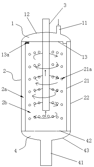
[0024] Embodiment one, as Figure 1 to Figure 2 as shown,

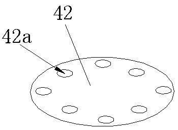
[0025] A gas-liquid separator, comprising a separator body, a steam chamber 1 is arranged on the upper part of the separator body, an air inlet pipe 11 is arranged on the steam chamber 1, and a cylindrical jacket 2 is arranged below the steam chamber 1, A water collection channel 2a is formed between the inner plate 21 and the outer plate 22 of the jacket 2, and a cylinder cavity 2b is formed in the middle of the separator body inside the inner plate 21 of the jacket 2, and the center of the cylinder cavity 2b is provided with The air outlet pipe 3, the upper end of the air outlet pipe 3 extends out of the separator body; the inner layer plate 21 of the jacket 2 is provided with a water outlet hole 21a, and the bottom of the jacket 2 is provided with a water collection chamber 4, and the water collection chamber 4 is connected with the The water collection channel 2a communicates with each other, the lower part of th...

Embodiment 2

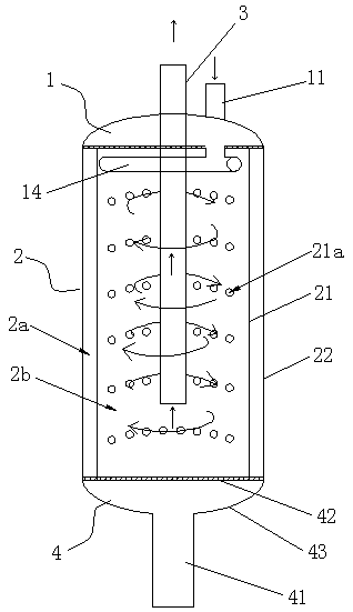
[0030] Embodiment two, such as Figure 3 to Figure 4 as shown,

[0031] The structure of the gas-liquid separator in this embodiment is similar to that in Embodiment 1, the difference is that in this embodiment, a vent pipe 14 is connected to the steam chamber 1, and the vent pipe 14 is placed on the upper part of the cylinder cavity 2b , and arranged along the diameter direction, the air inlet is the air outlet pipe 14a which is correspondingly arranged at both ends of the air pipe 14 .

[0032] In the embodiment, the air outlet pipe 14a is perpendicular to the ventilation pipe 14, and the air outlet pipes 14a at both ends face opposite directions. In this way, the steam enters the cylinder cavity 2b in a tangential direction, so as to obtain a greater linear velocity.

[0033] working principle:

[0034] The steam enters the steam chamber 1 from the air inlet pipe 11, and then enters the cylinder chamber 2b along the tangential direction from the air inlet arranged on the...


PUM


Abstract

The invention discloses a gas and liquid separator which comprises a separator body. A steam chamber is arranged at the upper portion of the separator body. A gas inlet pipe is arranged on the steam chamber, a jacket of the cylindrical structure is arranged below the steam chamber, a water collecting channel is formed between an inner layer plate and an outer layer plate of the jacket, a cylindercavity is formed inside an inner layer plate of the jacket at the middle of the separator body, a gas outlet pipe is arranged in the center of the cylinder cavity, and the upper end of the gas outletpipe stretches out of the separator body; a water outlet is formed in the inner layer plate of the jacket, a water collecting chamber is arranged below the jacket and communicated with the water collecting channel, a gas inlet is formed in the portion, at the inner side of the inner layer plate, of the outer edge of the steam chamber, and the gas inlet is formed in the tangent direction. The gas and liquid separator has the advantages of being simple in structure, high in separating efficiency and good in separating effect.

Description

technical field [0001] The invention relates to the technical field of steam-water separation, in particular to a gas-liquid separator. Background technique [0002] Gas-liquid separators are widely used in many fields such as boilers, chemical industry, food, petroleum processing, etc. The main function is to fully separate gas and liquid to obtain steam or other gases with higher purity. For example, the water vapor produced in the boiler usually contains water, or there will be condensed water after long-distance transportation, which has a great impact on some energy-consuming processes (such as ironing), so the liquid and steam must be separated; In the process of petroleum refining, it is necessary to separate the petroleum in a certain temperature range from the volatile components in that temperature range, and a gas-liquid separation device can also be used. The separation efficiency of the gas-liquid separator is very important. [0003] The gas-liquid separators...

Claims


Application Information

Patent Timeline
Patent Type & Authority Applications(China)
IPC IPC(8): B01D45/16B01D45/02B01D53/24
CPCB01D45/16B01D45/02B01D53/24B01D2257/80
Inventor 唐一波
Owner 宁波金名片能源科技有限公司
Why Eureka
Try Eureka