Building cement stirring mixing system and method

A technology for stirring and mixing, construction cement, applied in the field of mixing systems

Inactive Publication Date: 2019-07-30
陈常
View PDF12 Cites 17 Cited by
  • Summary
  • Abstract
  • Description
  • Claims
  • Application Information

AI Technical Summary

Problems solved by technology

[0002] For example, the publication number CN107718288A name is a kind of cement mixing and discharging device for building construction, which includes a main hollow shell. The bottom is provided with an inlet hole, and the inside of the main hollow shell is provided with a horizontal stirring and mixing section at the bottom of the inlet hole. The side of the main hollow shell is clamped and inlaid with an annular liquid injection mechanism, and the inside of the main hollow shell is provided with a connecting funnel. The hollow section and the main drain hole of the annular liquid injection mechanism; the disadvantage of this invention is that the cement cannot be mixed uniformly and comprehensively

Method used


Image

  • Building cement stirring mixing system and method
  • Building cement stirring mixing system and method
  • Building cement stirring mixing system and method

Examples


specific Embodiment approach 1

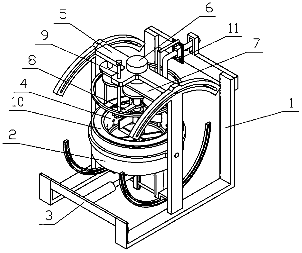
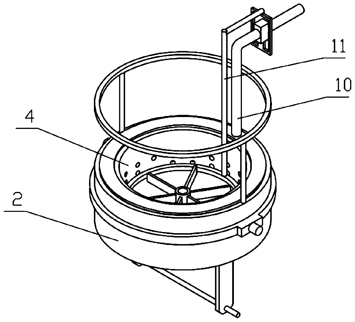
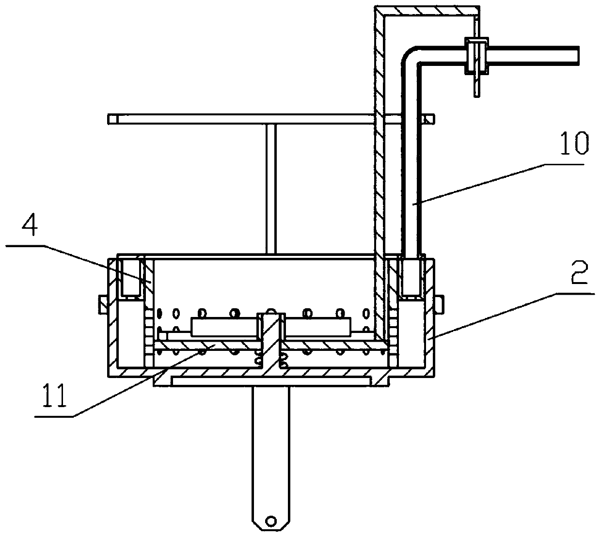
[0048] Combine below Figure 1-17 Describe this embodiment, a construction cement mixing and mixing system, including an integral support 1, a mixing support 2, a pushing mechanism 3, a mixing cylinder 4, a swinging support 5, a power mechanism 6, a planetary mechanism 7, a stirring mechanism 8, and a lifting screw 9 , the water inlet mechanism 10 and the sliding bracket 11, the middle part of the mixing bracket 2 is rotatably connected to the overall bracket 1, the lower end of the mixing bracket 2 is slidingly connected to the overall bracket 1, the pushing mechanism 3 is fixedly connected to the overall bracket 1, and the mixing bracket The lower end of 2 is slidably connected to the pushing mechanism 3, the mixing cylinder 4 is fixedly connected to the inner side of the mixing support 2, the swing support 5 is slidably connected to the overall support 1, the power mechanism 6 is fixedly connected to the swing support 5, and the planetary mechanism 7 is fixedly connected On...

specific Embodiment approach 2

[0050] Combine below Figure 1-17 Describe this embodiment, this embodiment will further explain the first embodiment, the overall bracket 1 includes a bottom plate 1-1, a support plate I1-2, a connecting plate 1-3, a support plate II1-4, and an arc plate I1-5 , arc groove I1-6, arc plate II1-7 and arc groove II1-8, two base plates 1-1 are provided, and the rear ends of the two base plates 1-1 are fixedly connected with support plate I1-2, A connection plate 1-3 is fixedly connected between the upper ends of the two support plates I1-2, a support plate II1-4 is fixedly connected to the middle parts of the two bottom plates 1-1, and the lower ends of the two support plates II1-4 are fixedly connected There are arc plates Ⅰ1-5, and arc grooves Ⅰ1-6 are arranged on the two arc plates Ⅰ1-5, and the upper ends of the two support plates Ⅱ1-4 are fixedly connected with arc plates Ⅱ1-7, and the two circles Arc grooves II1-8 are arranged on arc plates II1-7; the centers of arc plates ...

specific Embodiment approach 3

[0052] Combine below Figure 1-17 Describe this embodiment, this embodiment will further explain Embodiment 2, the mixing bracket 2 includes a mixing outer cylinder 2-1, a rotating ring 2-2, a swing plate 2-3, a swing rod 2-4, and a swing support ring 2-5, mixing shaft 2-6, mixing impeller 2-7, connecting rod 2-8 and ring gear 2-9, the lower end of mixing outer cylinder 2-1 is connected with rotating ring 2-2, rotating ring 2-2 The lower end of the swing plate 2-3 is fixedly connected with a swing plate 2-3, and the lower end of the swing plate 2-3 is fixedly connected with a swing rod 2-4, and the two ends of the swing rod 2-4 are respectively slidably connected in two arc grooves I1-6, mixing The outer cylinder 2-1 is rotatably connected with a swing support ring 2-5, and the two ends of the swing support ring 2-5 are respectively rotatably connected with two support plates II 1-4, and the inside of the mixing outer cylinder 2-1 is fixedly connected with a mixing Shaft 2-6,...


PUM


Abstract

The invention relates to a mixing system and method, in particular to a building cement stirring mixing system and method. The system comprises a whole support, a mixing support, a pushing mechanism,a mixing cylinder, a swing support, a power mechanism, a planetary mechanism, a stirring mechanism, a lifting screw, a water inlet mechanism and a sliding support; through the power mechanism, the mixing support and the stirring mechanism are driven at the same time to rotate at the same time, the mixing support and the stirring mechanism are opposite in rotation direction to mix and stir the cement raw material in the mixing cylinder, the pushing mechanism is combined for pushing the mixing support to swing, due to the fact that centrifugal force generated by rotating of the mixing support and the stirring mechanism has the tendency of pushing a cement raw material mixture to the outer side, when the pushing mechanism pushes the mixing support to swing, the gravity center of the cement raw material mixture is repeatedly changed, the cement raw material mixture is prevented from being stacked on the outer ring in the mixing cylinder, and the mixing and stirring effect is improved.

Description

technical field [0001] The invention relates to a mixing system and method, more specifically to a construction cement mixing system and method. Background technique [0002] For example, the publication number CN107718288A name is a kind of cement mixing and discharging device for building construction, which includes a main hollow shell. The bottom is provided with an inlet hole, and the inside of the main hollow shell is provided with a horizontal stirring and mixing section at the bottom of the inlet hole. The side of the main hollow shell is clamped and inlaid with an annular liquid injection mechanism, and the inside of the main hollow shell is provided with a connecting funnel. The hollow section and the main liquid discharge hole of the annular liquid injection mechanism; the shortcoming of this invention is that the cement cannot be mixed and stirred uniformly and comprehensively. Contents of the invention [0003] The object of the present invention is to provid...

Claims


Application Information

Patent Timeline
Patent Type & Authority Applications(China)
IPC IPC(8): B28C5/48B28C7/12B28C5/00
CPCB28C5/006B28C5/485B28C7/126
Inventor 陈常
Owner 陈常
Why Eureka
Try Eureka