Eureka AIR delivers breakthrough ideas for toughest innovation challenges, trusted by R&D personnel around the world.

Locomotive brake control system and method

A brake control and locomotive technology, applied in the direction of brake safety systems, brakes, brake components, etc., can solve the problem that the train pipe pressure cannot be controlled

Active Publication Date: 2019-07-30
CRRC QINGDAO SIFANG ROLLING STOCK RES INST
View PDF8 Cites 12 Cited by
  • Summary
  • Abstract
  • Description
  • Claims
  • Application Information

AI Technical Summary

Problems solved by technology

[0004] Aiming at the technical problem in the prior art that the train pipe pressure cannot be controlled due to a fault in the balance air cylinder pressure control, the present invention provides a locomotive brake control system, which can prevent the failure of the balance air cylinder pressure control leading to the train pipe pressure. When the pressure cannot be controlled, redundant control is performed on the train tube, thereby ensuring the braking performance of the locomotive and subsequent vehicles, and improving the safety and reliability of the railway vehicle

Method used


Image

  • Locomotive brake control system and method
  • Locomotive brake control system and method
  • Locomotive brake control system and method

Examples


no. 1 example

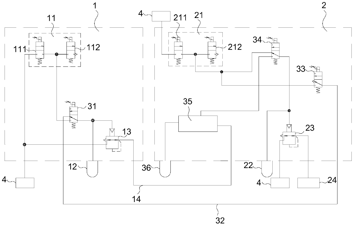
[0036] A locomotive brake control system, comprising a train pipe brake control module 1 and a brake cylinder brake control module 2, the train pipe brake control module 1 includes a first pressure control valve 11, an equalizing air cylinder 12, a first The relay valve 13 and the train pipe 14; the brake cylinder brake control module 2 includes the second pressure control valve 21, the pre-control air cylinder 22, the second relay valve 23 and the brake cylinder 24 connected in sequence; also includes the train The tube redundant brake control module, the train tube redundant brake module is connected between the equalizing air cylinder 12 and the second pressure control valve 21 and the pre-control air cylinder 22 .

[0037] The locomotive braking control system provided in the first embodiment is provided with a train management redundant braking control module, and the train management redundant braking control module is connected between the train management braking contro...

no. 2 example

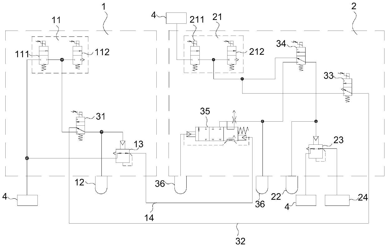
[0057]The present invention also provides a second embodiment. In the second embodiment, a distribution valve is used as the mechanical distribution valve 35. For the specific structure of the distribution valve, please refer to CN2017104076361. There are two working air cylinders 36, and the two working air cylinders 36 are connected with distribution valves.

[0058] All the other parts are the same as the first embodiment.

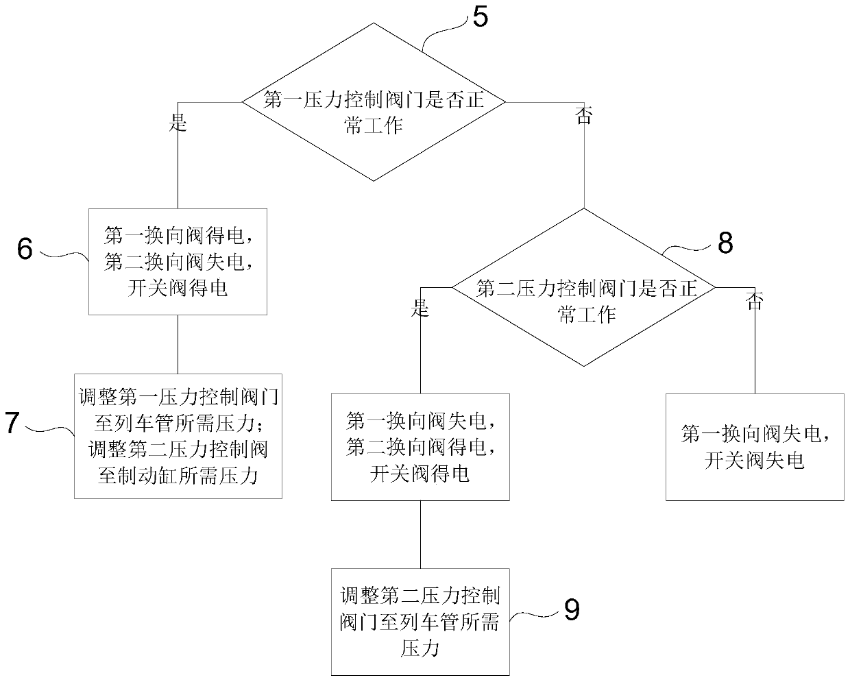
[0059] An embodiment of the present invention also provides a locomotive braking control method, using the above-mentioned locomotive braking control system, including the following steps:

[0060] Step 1: Detect whether the first pressure control valve 11 works normally; if it works normally, go to step 2; if not, go to step 4;

[0061] Step 2: Disconnect the channel connection between the redundant brake control module of the train pipe and the equalizing air cylinder 12, and connect the first pressure control valve 11 with the equalizing air cylinde...


PUM


Abstract

The invention provides a locomotive brake control system, which comprises a train pipe brake control module and a brake cylinder brake control module. The train pipe brake control module comprises a first pressure control valve, an equalizing air cylinder, a first relay valve, and a train pipe which are successively connected; the brake cylinder module comprises a second pressure control valve, apre-control air cylinder, a second relay valve, and a brake cylinder which are connected successively; and the locomotive brake control system further comprises a train pipe redundant brake control module, wherein the train pipe redundant brake control module is connected between the equalizing air cylinder and the second pressure control valve. The invention further provides a locomotive brake control method. According to the locomotive brake control system and method, when pressure to the train pipe is out of control due to fault of pressure control of the equalizing air cylinder, the trainpipe is controlled redundantly, thus braking performance of locomotives and subsequent vehicles is ensured, and safety and reliability of railway vehicles are improved.

Description

technical field [0001] The invention belongs to the field of railway train braking control systems, and in particular relates to a locomotive braking control system and method. Background technique [0002] In the locomotive brake control system, by controlling the pressure value of the balance air cylinder, the pressure control of the train pipe is realized, and then the braking control of the subsequent vehicles is realized. Therefore, the reliability of the equalizing air cylinder pressure control directly affects the pressure control of the locomotive brake system on the train tube, and further affects the braking performance of the locomotive and subsequent vehicles. [0003] If the pressure control of the equalizing air cylinder fails, for example, the solenoid valve for filling and exhausting the equalizing air cylinder fails or the control module of the train pipe loses power, etc., the pressure input to the equalizing air cylinder cannot be controlled, which further...

Claims


Application Information

Patent Timeline
Patent Type & Authority Applications(China)
IPC IPC(8): B61H11/10B60T17/18B60T17/22
CPCB60T17/18B60T17/228B61H11/10
Inventor 王帅帅任向杰王令军吕枭王程成孙伟健侯化安
Owner CRRC QINGDAO SIFANG ROLLING STOCK RES INST
Why Eureka
Eureka Blog
Learn More