Film slitting efficient slitting machine with blade conveniently replaced

A film slitting, high-efficiency technology, applied in the direction of thin material processing, sending objects, transportation and packaging, etc., can solve the problem of reducing the feeding rate of the slitting machine, the total weight of the support shaft and the film, and reducing the maintenance of the slitting machine. It can improve the speed of feeding, improve convenience and simple structure.

Active Publication Date: 2019-07-30
浙江创富新材料有限公司
View PDF7 Cites 2 Cited by
  • Summary
  • Abstract
  • Description
  • Claims
  • Application Information

AI Technical Summary

Problems solved by technology

[0003] The blades of the cutting machine in the prior art are mostly disc-shaped. During the installation process, multiple blades are sleeved on the same shaft. When one of the blades is damaged, the operator needs to disassemble the blade located on the side of the blade Multiple blades are required to replace the blade, which reduces the convenience of slitter maintenance. Not only that, a large amount of film is wound on the support shaft between the slitter and the film, so the distance between the support shaft and the film The total weight is heavy, so when the operator installs the support shaft on the slitting machine, not only tools are needed, but also multiple people are required to operate at the same time, which reduces the feeding speed of the slitting machine and reduces the working efficiency of the slitting machine

Method used


Image

  • Film slitting efficient slitting machine with blade conveniently replaced
  • Film slitting efficient slitting machine with blade conveniently replaced
  • Film slitting efficient slitting machine with blade conveniently replaced

Examples


Embodiment Construction

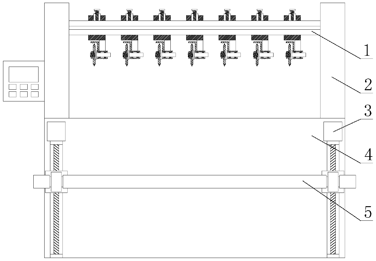
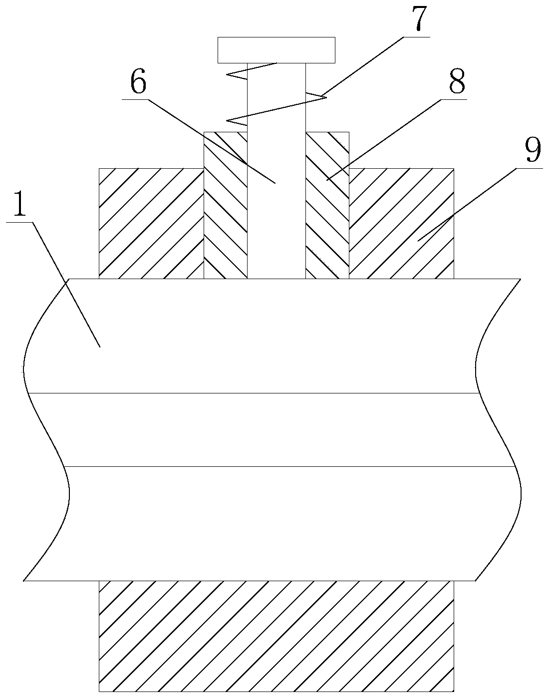
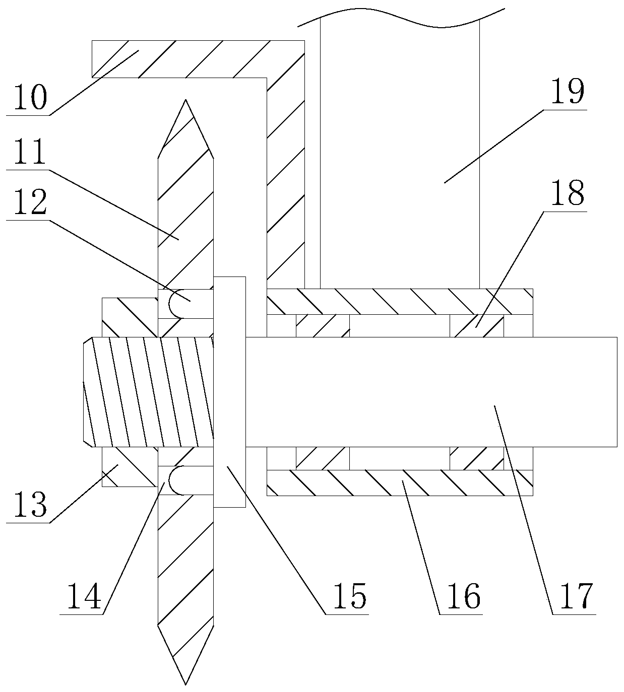
[0026] The present invention is described in further detail now in conjunction with accompanying drawing. These drawings are all simplified schematic diagrams, which only illustrate the basic structure of the present invention in a schematic manner, so they only show the configurations related to the present invention.

[0027] Such as figure 1 As shown, a high-efficiency slitting machine that is convenient for blade replacement for film slitting includes a base 4, a guide rail 1 and two supports 2, and the support 2 is arranged on one side of one end of the base 4, and the guide rail 1 is perpendicular to the bracket 2, one end of the guide rail 1 is fixedly connected to the bracket 2, and also includes a feeding mechanism and at least two cutting mechanisms, the feeding mechanism is arranged on one side of the base 4, and each cutting mechanism is arranged in a row on rail 1;

[0028] The convenience of film raw material feeding is improved by the feeding mechanism, the sp...


PUM


Abstract

The invention relates to a film slitting efficient slitting machine with a blade conveniently replaced. The film slitting efficient slitting machine comprises a base, a guide rail and two supports andfurther comprises a feeding mechanism and at least two slitting mechanisms. Each slitting mechanism comprises a moving assembly, a connecting rod, a rotating shaft, a supporting casing pipe, a supporting plate, a blade, a fixing block and two bearings. The feeding mechanism comprises a supporting shaft and two lifting assemblies. Each lifting assembly comprises a drive unit, a lifting base, a supporting block and a sliding rod. Each moving assembly comprises a moving casing pipe, a fixed casing pipe, a limiting rod and a spring. Each drive unit comprises a motor and a screw rod. By means of the film slitting efficient slitting machine with the blade conveniently replaced, the feeding convenience of film raw materials is improved through the feeding mechanism, the feeding speed of the slitting machine is increased, the work efficiency of the slitting machine is improved, the blade replacing convenience is improved through the slitting mechanisms, and the convenience of slitting machinemaintenance is improved.

Description

technical field [0001] The invention relates to the field of film production equipment, in particular to a high-efficiency slitting machine for film slitting that is convenient for blade replacement. Background technique [0002] The slitting machine is a kind of mechanical equipment that cuts wide paper, mica tape or film into multiple narrow-width materials. It is often used in papermaking machinery, wire and cable mica tape and printing and packaging machinery. The slitting machine is mainly used in: Slitting of woven fabrics, mica tapes, paper, insulating materials and various film materials, especially suitable for slitting of narrow non-woven fabrics, paper, insulating materials, mica tapes, films, etc. [0003] The blades of the cutting machine in the prior art are mostly disc-shaped. During the installation process, multiple blades are sleeved on the same shaft. When one of the blades is damaged, the operator needs to disassemble the blade located on the side of the ...

Claims


Application Information

Patent Timeline
IPC IPC(8): B65H35/02
CPCB65H35/02
Inventor 包宇峰
Owner 浙江创富新材料有限公司
Why Eureka
Try Eureka