Efficient lightweight speed reducer for tower crane

A lightweight, reducer technology, applied in the direction of clockwork mechanism, mechanical equipment, transmission parts, etc., can solve the problem that it is not easy to ensure the shape and position tolerance of parallel and perpendicular bearing holes, it is not easy to ensure the machining accuracy of bearing holes, and affect the work Efficiency and bearing life and other issues, to achieve the effect of lightweight design, reduce the risk of oil leakage, and reduce the joint surface of the box

Pending Publication Date: 2019-07-30
CHENGDU JIUHE CONSTR EQUIP
View PDF0 Cites 10 Cited by
  • Summary
  • Abstract
  • Description
  • Claims
  • Application Information

AI Technical Summary

Problems solved by technology

[0002] The traditional reducer box is a separated upper and lower box, the wall thickness is thicker and the box is relatively heavy. At the same time, the separated upper and lower box is not easy to ensure the machining accuracy of the bearing holes, and it is not easy to ensure the parallel and perpendicular bearing holes. Shape and position tolerance, there is a risk of oil leakage on the upper and lower joint surfaces of the box
In addition, the lack of lubricating oil circulating oil circuit inside the traditional reducer leads to insufficient lubrication of the bearings, especially the high-speed end bearings of the reducer, which have high speed and high calorific value. Due to the lack of circulating lubricating oil, the heat is taken away, resulting in The high temperature of the bearing housing at the high-speed end greatly affects the working efficiency and bearing life
Moreover, the connection between the output shaft of the traditional reducer and the drum of the tower crane adopts a straight shaft flat key structure, and tooling is required to press (pull out) the drum sleeve into the output shaft of the reducer during assembly (disassembly), which is difficult to assemble and disassemble

Method used


Image

  • Efficient lightweight speed reducer for tower crane
  • Efficient lightweight speed reducer for tower crane
  • Efficient lightweight speed reducer for tower crane

Examples


Embodiment Construction

[0043] The present invention will be described in detail below in conjunction with the drawings.

[0044] In order to make the objectives, technical solutions and advantages of the present invention clearer, the following further describes the present invention in detail with reference to the accompanying drawings and embodiments. It should be understood that the specific embodiments described here are only used to explain the present invention, but not to limit the present invention.

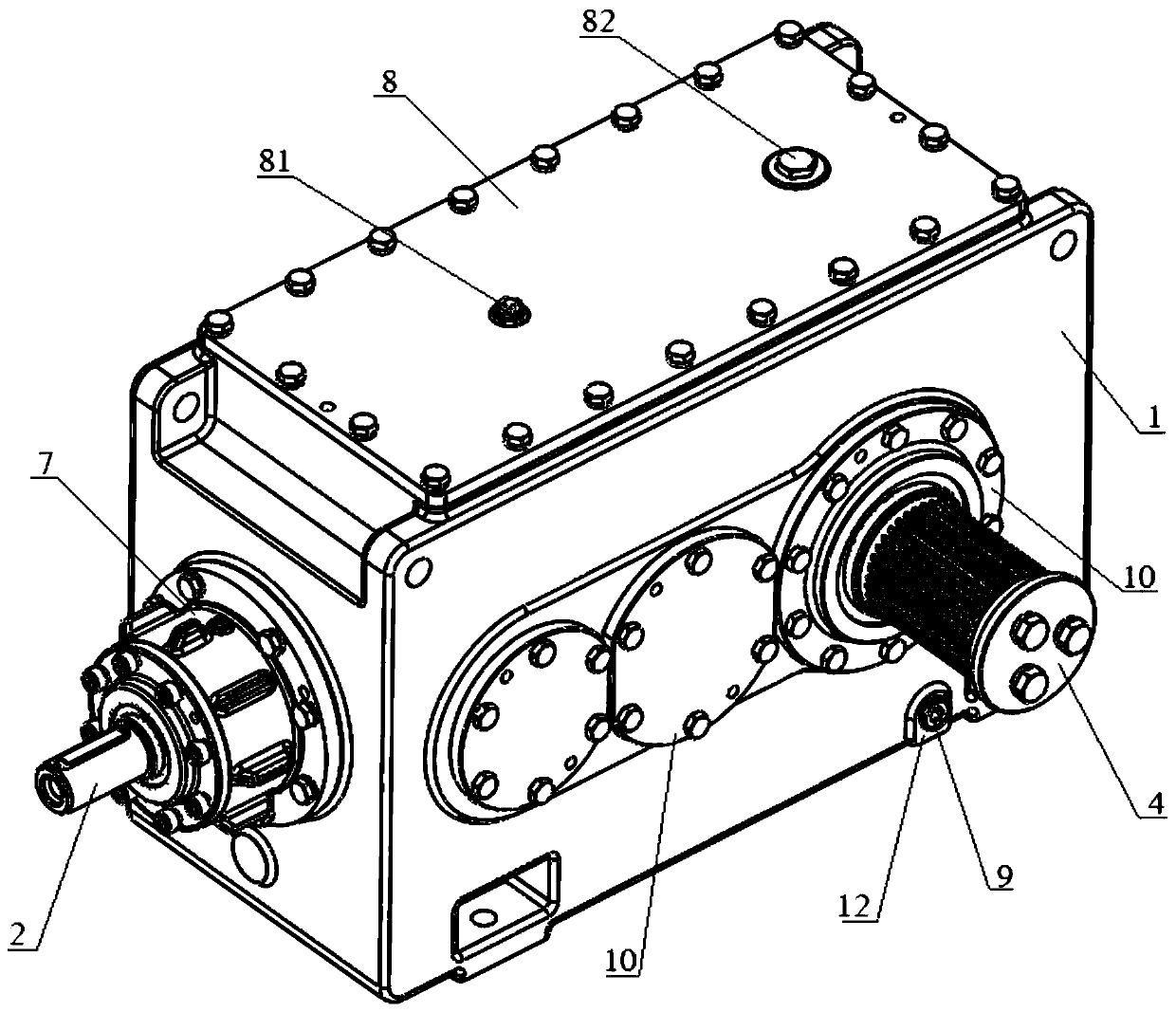
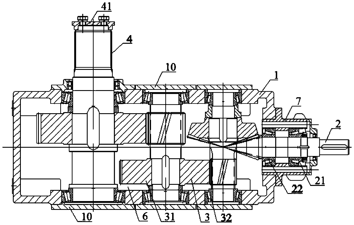
[0045] Such as figure 1 with image 3 As shown, an efficient and lightweight reducer for a tower crane includes a box body 1, and an input shaft 2, a transmission assembly 3, and an output shaft 4 mounted on the box body 1, the input shaft 2, the transmission assembly 3 and the output shaft 4 mesh and drive in turn. The housing 1 is connected with a high-speed end bearing seat 7, the input shaft 2 is mounted on the high-speed end bearing seat 7 through a first high-speed bearing 21 and a second hig...


PUM


Abstract

The invention discloses an efficient lightweight speed reducer for a tower crane. The speed reducer comprises a whole box body, an input shaft, a transmission assembly and an output shaft, wherein theinput shaft, the transmission assembly and the output shaft are sequentially engaged for transmission, the end, extending out of the box body, of the output shaft is of a spline structure, a first convex stop opening is preset on a cover plate of the output shaft and is matched with a first concave stop opening of a winding cylinder spline sleeve, and a second convex stop opening is preset on anouter circle shaft of the end, extending out of the box body, of the output shaft, and is matched with a second concave stop opening of the winding cylinder spline sleeve; an oil tank is formed in thebox body, the inner wall of the oil tank forms a first oil collection groove and a first oil way, the first oil way passes through the transmission assembly and/or a bearing of the output shaft, oneend of the first oil way communicates with the first oil collection groove, the other end of the first oil way communicates with an oil tank inner cavity, the box body is connected with a high-speed end bearing pedestal, a second oil collection groove and a second oil way are formed on the high-speed end bearing pedestal, the second oil way passes through an inner cavity of the high-speed end bearing pedestal, one end of the second oil way communicates with the second oil collection groove, and the other end of the second oil way communicates with the oil tank inner cavity.

Description

Technical field [0001] The invention relates to a reducer, in particular to an efficient and lightweight reducer for tower cranes. Background technique [0002] The traditional reducer case is a separate upper and lower case, with thicker walls and bulkier. At the same time, the separate upper and lower case is not easy to ensure the machining accuracy of the bearing holes, and it is not easy to ensure the parallel and right angle bearing holes. Shape and position tolerance, there is a risk of oil leakage on the upper and lower joint surfaces of the box. In addition, the lack of a lubricating oil circulating oil circuit in the traditional reducer leads to insufficient lubrication of the bearings, especially the high-speed end bearings of the reducer, which have high speed and large heat generation. The lack of circulating lubricating oil will take away the heat. The high temperature of the high-speed end bearing seat greatly affects the working efficiency and bearing life. More...

Claims


Application Information

Patent Timeline
Patent Type & Authority Applications(China)
IPC IPC(8): B66D1/14F16H57/038F16H57/021F16H57/023F16H57/027F16H57/028F16H57/031F16H57/00F16H57/04
CPCB66D1/14F16H57/0018F16H57/021F16H57/023F16H57/027F16H57/028F16H57/031F16H57/038F16H57/0402F16H57/0404F16H57/0408F16H57/0423F16H57/0424F16H57/0449F16H57/045F16H2057/02069
Inventor 程华祝丽蓉杜娟黄杰代建均吴华传肖开波杨泓王文左刚
Owner CHENGDU JIUHE CONSTR EQUIP
Why Eureka
Try Eureka