Eureka AIR delivers breakthrough ideas for toughest innovation challenges, trusted by R&D personnel around the world.

Two-dimensional straightness error and position simultaneous measuring apparatus and method

A technology of straightness error and measuring device, applied in the direction of measuring device, optical device, instrument, etc., can solve the problem that the position of the measuring point cannot be given at the same time, achieve simultaneous measurement, meet high-efficiency requirements, and ensure normal generation Effect

Active Publication Date: 2019-07-30
ZHEJIANG SCI-TECH UNIV
View PDF6 Cites 0 Cited by
  • Summary
  • Abstract
  • Description
  • Claims
  • Application Information

AI Technical Summary

Problems solved by technology

[0003] In order to solve the technical problem that the position of the straightness error measurement point cannot be given at the same time in the traditional laser straightness measurement technology, the present invention combines the laser spot position measurement theory and the laser interference theory to provide a two-dimensional straightness error and its Simultaneous position measurement method, which can realize simultaneous measurement of three degrees of freedom parameters of horizontal straightness error, vertical straightness error and straightness error measurement point position

Method used


Image

  • Two-dimensional straightness error and position simultaneous measuring apparatus and method
  • Two-dimensional straightness error and position simultaneous measuring apparatus and method
  • Two-dimensional straightness error and position simultaneous measuring apparatus and method

Examples


Embodiment Construction

[0041] The present invention will be further described below in conjunction with drawings and embodiments.

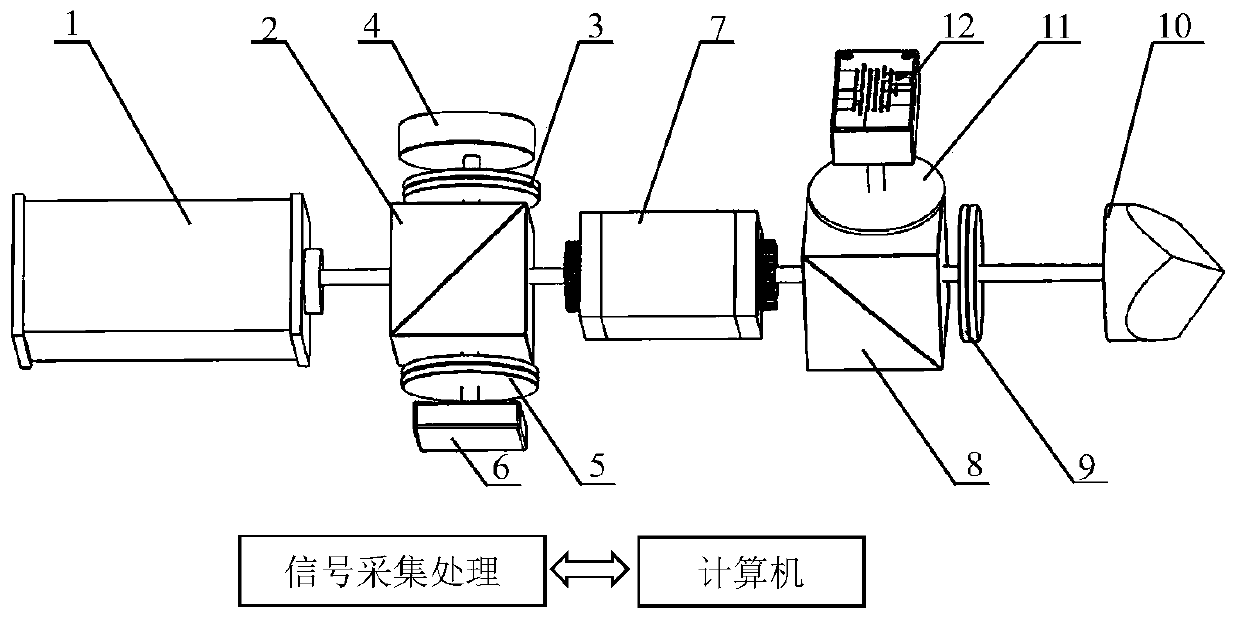
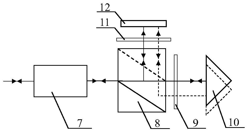
[0042] Optical path structure of the present invention such as figure 1 As shown, it includes the laser spot position detection optical path and the laser heterodyne interference position measurement optical path. The specific implementation process is as follows:

[0043] A) Laser spot position detection optical path part

[0044] The laser spot position detection optical path part includes a half mirror 11 and a position sensitive detector 12 . The light reflected by the corner cube prism 10 is transmitted through the second quarter-wave plate 9 , reflected by the second polarizing beam splitter 8 , and is incident on the half mirror 11 . Part of the light reflected by the half-mirror 11 is used to generate a retrograde measuring beam, and the light transmitted by the half-mirror 11 is incident on the position-sensitive detector 12, and by detecting the light spot i...


PUM


Abstract

The present invention discloses a two-dimensional straightness error and position simultaneous measuring apparatus and method. The method is characterized in that: a corner cube is used as a measuringmirror of a three-degree-of-freedom measurement optical path; a spot position signal generated by a laser spot position detection optical path is subjected to signal acquisition and data processing,so that measurement of the horizontal straightness error and the vertical straightness error are implemented; and an interference signal generated by a laser heterodyne interference position measurement optical path is subjected to signal acquisition and data processing, so that measurement of the position of the straightness error measurement point is implemented. According to the technical scheme of the present invention, not only simultaneous measurement of the horizontal and vertical straightness errors can be implemented, but also the position of the straightness error measurement point can be given, so that the technical scheme can be used for measuring and calibrating the straightness parameters of the large stroke precision guide rail, the precision worktable, and the like, and thedetection efficiency can be improved.

Description

technical field [0001] The invention relates to a device and method for simultaneous measurement of multi-degree-of-freedom parameters in the field of precision geometric quantity measurement, in particular to a device and method for simultaneous measurement of two-dimensional straightness error and its position. Background technique [0002] In ultra-precision machining and manufacturing, high-precision geometric measurement is the key to ensure precision machining and manufacturing accuracy. The interference, linearity, and traceability of the length reference make laser technology the main technical means used in geometric quantity detection. The traditional laser interferometer uses the supporting straightness measurement components. Although the straightness measurement can be realized, the horizontal straightness and vertical straightness measurements need to be carried out in time, and only one-dimensional straightness measurement can be realized each time. In additio...

Claims


Application Information

Patent Timeline
Patent Type & Authority Applications(China)
IPC IPC(8): G01B11/00G01B11/27
CPCG01B11/00G01B11/272
Inventor 张恩政陈本永
Owner ZHEJIANG SCI-TECH UNIV
Why Eureka
Eureka Blog
Learn More