Double-barrel gas-liquid separator

A gas-liquid separator and separator technology, which is applied in separation methods, dispersed particle separation, liquid degassing, etc., can solve the problems of single applicable flow pattern, small separator usable range, and inability to oscillate the efficient operation of the flow pattern, etc., to achieve Guarantee the effect of efficient operation and efficient separation

Inactive Publication Date: 2019-08-02
HARBIN ENG UNIV
View PDF7 Cites 6 Cited by
  • Summary
  • Abstract
  • Description
  • Claims
  • Application Information

AI Technical Summary

Problems solved by technology

[0005] The purpose of the present invention is to provide a double-barrel gas-liquid separator that solves the problems of the existing separator

Method used


Image

  • Double-barrel gas-liquid separator
  • Double-barrel gas-liquid separator
  • Double-barrel gas-liquid separator

Examples


Embodiment Construction

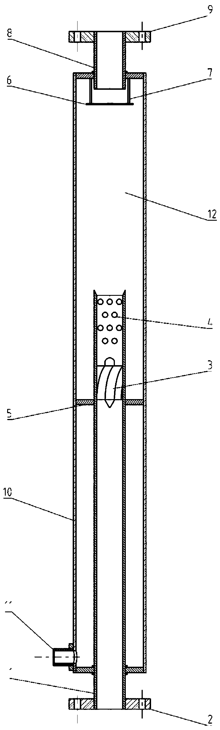
[0022] The present invention is described in more detail below in conjunction with accompanying drawing example:

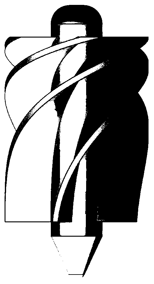
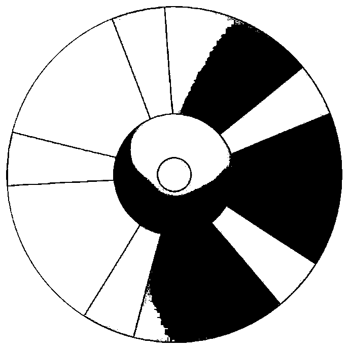
[0023] combine Figure 1-3 , a double-barrel gas-liquid separator of the present invention, including an inner cylinder body 1, an inlet flange 2, an impeller 3, a liquid discharge section 4, an anti-vibration strip 5, a separation baffle 6, a separation baffle tie bar 7, and a separator Gas phase outlet 8, outlet flange 9, outer cylinder 10, separator liquid phase outlet 11, gravity separation chamber 12. The gas phase outlet 8 of the separator is located at the top of the separator, and the liquid phase outlet 11 is located at the bottom of the outer cylinder 10; the inlet end of the gas-liquid mixture of the inner cylinder 1 is located outside the outer cylinder 10, and the outlet end is located at the outer cylinder 10 inside; the impeller 3 is arranged in the middle and upper part of the inner cylinder 1, and a liquid discharge section 4 is arranged between ...


PUM


Abstract

The invention aims at providing a double-barrel gas-liquid separator. The double-barrel gas-liquid separator comprises an outer barrel body, and an inner barrel body which extends into the outer barrel body, wherein the lower end part of the inner barrel body is kept at the outer part of the outer barrel body; an impeller is mounted in the inner barrel body; a liquid draining area section is arranged at the outlet end of the inner barrel body; a liquid draining hole is formed in the liquid draining area section; a separator liquid phase guide outlet is formed in the lower end part of the outerbarrel body; a separator gas phase guide outlet which is a pipe extending into the outer barrel body is formed in the top part of the outer barrel body; a separating baffle plate is arranged in the outer barrel body at the lower part of the separator gas phase guide outlet, and the separating baffle plate is connected to the outer barrel body at the upper part through a separating baffle plate pulling rib; the outer barrel body at the upper part of the inner barrel body forms a gravity separating chamber through which a liquid phase flows back. The double-barrel gas-liquid separator organically combines three separating theories, including the centrifuging separating theory, gravity separating theory and collision separating theory; the double-barrel gas-liquid separator is small in size,and compact in structure and is capable of effectively separating gas-liquid mixtures in wide gas phase and liquid phase process.

Description

technical field [0001] The invention relates to a gas-liquid separator. Background technique [0002] Gas-liquid separation technology is widely used in the exploitation of offshore oil and gas resources. It is of great significance to develop a gas-liquid separator that is small in size, compact in structure, and can operate efficiently under wide flow and multi-flow patterns. [0003] At present, there are many kinds of gas-liquid separators that have been practically applied in actual industrial production. According to the separation principle, they can be divided into the following categories: gravity gas-liquid separator, centrifugal gas-liquid separator, collision gas-liquid separator and combination type gas-liquid separator. Gravity-type gas-liquid separator is a well-studied and well-developed separator. It is widely used due to its high reliability and convenient maintenance. However, it is limited by large structural size, long separation period, and limited pro...

Claims


Application Information

Patent Timeline
IPC IPC(8): B01D45/14B01D45/02B01D45/08B01D19/00E21B43/34
CPCB01D19/00B01D45/02B01D45/08B01D45/14E21B43/34
Inventor 阎昌琪范广铭王建军王刚曾晓波刘安泰徐浚修
Owner HARBIN ENG UNIV
Why Eureka
Try Eureka