Flow-guiding anti-splashing mechanism for preventing cooling water from splashing out of water tank
A technology of cooling water and splashing, which is applied in the field of machine tool bed, which can solve the problems of cooling water splashing out of the water tank, and achieve the effects of preventing splashing out of the water tank, reducing pollution, and reducing impact
- Summary
- Abstract
- Description
- Claims
- Application Information
AI Technical Summary
Problems solved by technology
Method used
Image

Examples
Embodiment 1
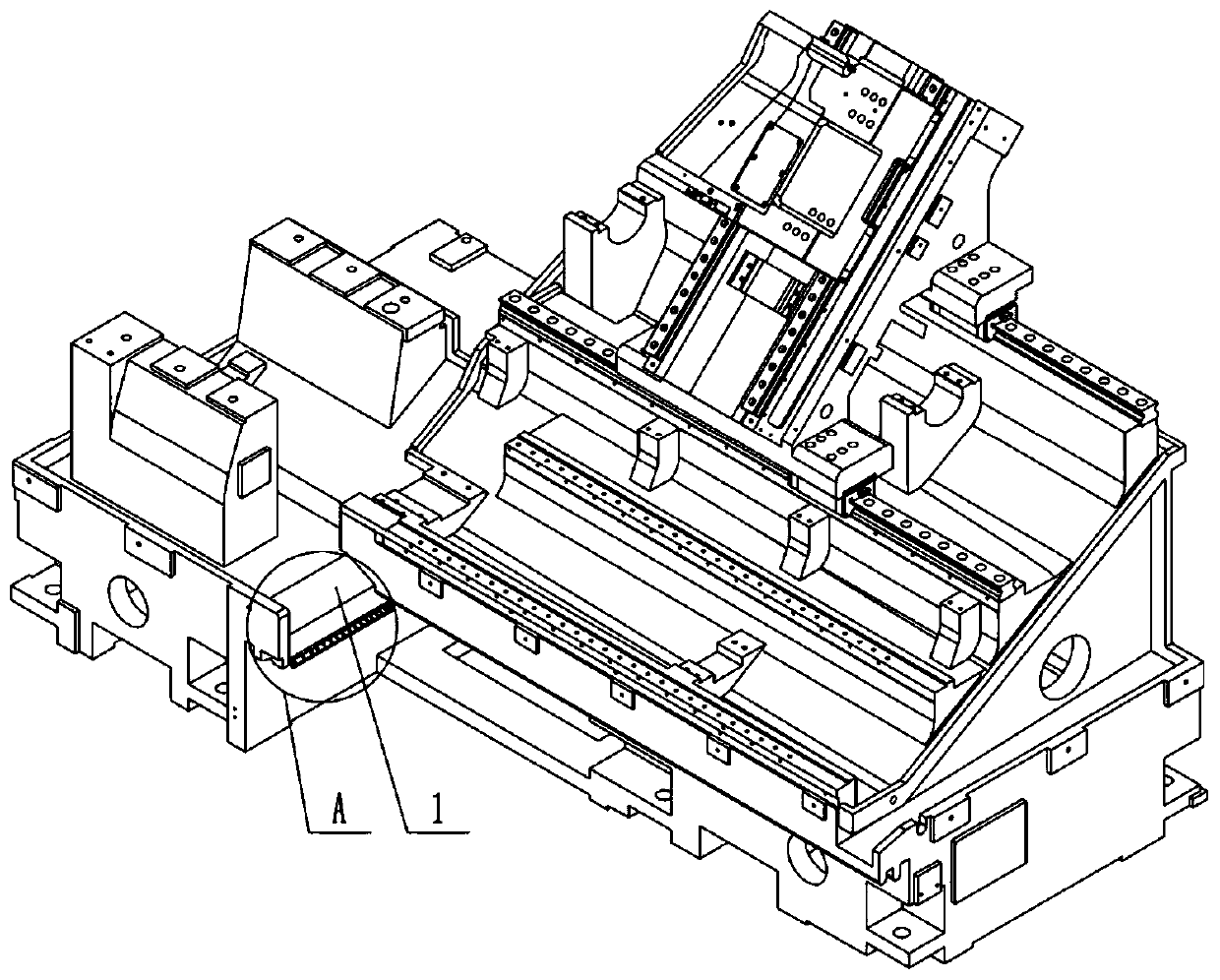
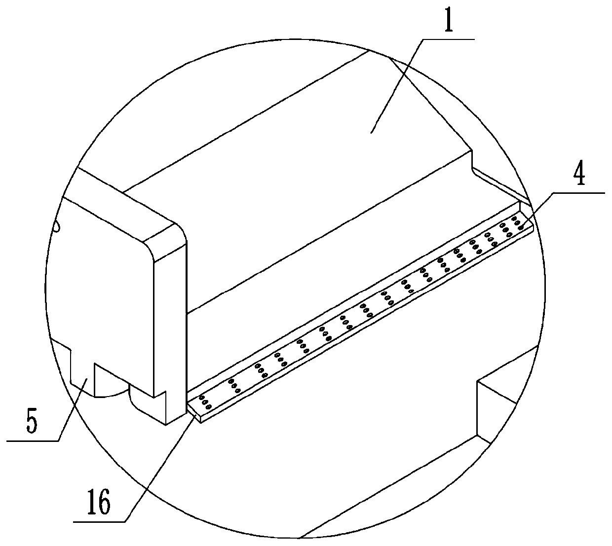
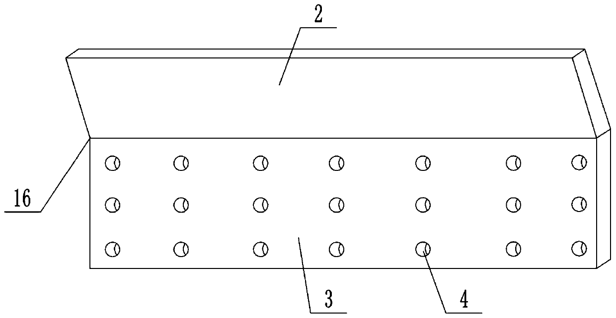
[0039] A diversion and splash prevention mechanism for preventing cooling water from splashing out of a water tank, mainly composed of a diversion unit and a splash prevention unit. combined with figure 1 , attached figure 2 And attached image 3As shown, the flow guide unit is mainly composed of a guide splitter plate 16 and a number of first leakage holes 4. The bottom end of the right part of the cooling water artesian part 1 is integrally formed or installed with a guide splitter plate 16. The guide splitter plate 16 is L-shaped. Splitter plate 16 comprises vertically arranged guide part 2 and laterally arranged splitter part 3, and the distance from the top right side of guide part 2 to the right end of cooling water artesian part 1 is 1.5-4cm, preferably 2cm; The guide part 2 is integrally formed and located at the lower left of the cooling water artesian part 1, and the right end of the diversion part 3 is located at the lower right of the cooling water artesian part...
Embodiment approach
[0041] The specific implementation is: after the cooling water flows to the cooling water artesian part 1, part of the cooling water will gradually flow along the bottom surface of the cooling water artesian part 1 to the guide part 2 of the guide diverter plate 16, and then gradually flow from the guide part 2 to the diverter part In each of the first leakage holes 4 of 3, the cooling water is divided into several streams, which reduces the gravity of a single stream of water. In the case of the same height difference, the gravitational potential energy of a single stream of water formed after being divided is reduced. The small size reduces the impact on the cooling water in the water tank when the cooling water flows into the water tank, so that it is difficult for the cooling water to splash when it flows into the water tank, thereby preventing the cooling water from splashing out of the water tank.
[0042] Part of the cooling water flowing down from the guide portion 2 ma...
Embodiment 2
[0046] The difference between this embodiment and Embodiment 1 is that in this embodiment, a side hole is opened laterally on the right side of each first leakage hole 4, combined with the attached Figure 6 And attached Figure 7 As shown, an L-shaped insertion rod 12 is inserted in the side hole, and a sealing ring is arranged between the insertion rod 12 and the side hole. combined with Figure 8 As shown, the bottom end of the insertion rod 12 is integrally formed or equipped with a diverter plate 13, which is used to further divert the cooling water. The axis of the diverter plate 13 coincides with the axis of the first leakage hole 4. Below the first leak hole 4, and the diameter of the diverter plate 13 is smaller than the diameter of the first leak hole 4, such design can ensure that the edge of the first leak hole 4 has a vertical water flow down, thereby blocking the cooling water along the guide diverter plate 16 bottoms spread toward splash-proof groove 11 direct...
PUM
 Abstract
Description
Claims
Application Information
 - R&D
- Intellectual Property
- Life Sciences
- Materials
- Tech Scout
- Unparalleled Data Quality
- Higher Quality Content
- 60% Fewer Hallucinations
Browse by: Latest US Patents, China's latest patents, Technical Efficacy Thesaurus, Application Domain, Technology Topic, Popular Technical Reports.
© 2025 PatSnap. All rights reserved.Legal|Privacy policy|Modern Slavery Act Transparency Statement|Sitemap|About US| Contact US: help@patsnap.com