Supercharge Your Innovation With Domain-Expert AI Agents!

Safe automatic drainage system

An automatic drainage and safety technology, applied in the water supply pipeline system, water supply equipment, water supply main pipeline, etc., can solve the problems that cannot meet the needs of production, safety hazards, cooling water spillage, etc., achieve low cost and reduce safety risks , the effect of simple operation

Pending Publication Date: 2019-08-02
GUANGZHOU SONGXING ELECTRIC
View PDF0 Cites 0 Cited by
  • Summary
  • Abstract
  • Description
  • Claims
  • Application Information

AI Technical Summary

Problems solved by technology

In mechanical automation, it is often necessary to use cooling water to cool down the equipment so that the mechanical equipment can run safely and stably. However, if a part of the waterway in the cooling system is damaged or needs to be replaced, the main method is to directly remove the parts manually, but When the parts are removed, the cooling water in the waterway will spill out, which will bring potential safety hazards and easily cause safety problems, which can no longer meet the needs of production. Therefore, it is necessary to improve the existing drainage system to solve the above problems

Method used


Image

  • Safe automatic drainage system
  • Safe automatic drainage system
  • Safe automatic drainage system

Examples


Embodiment 1

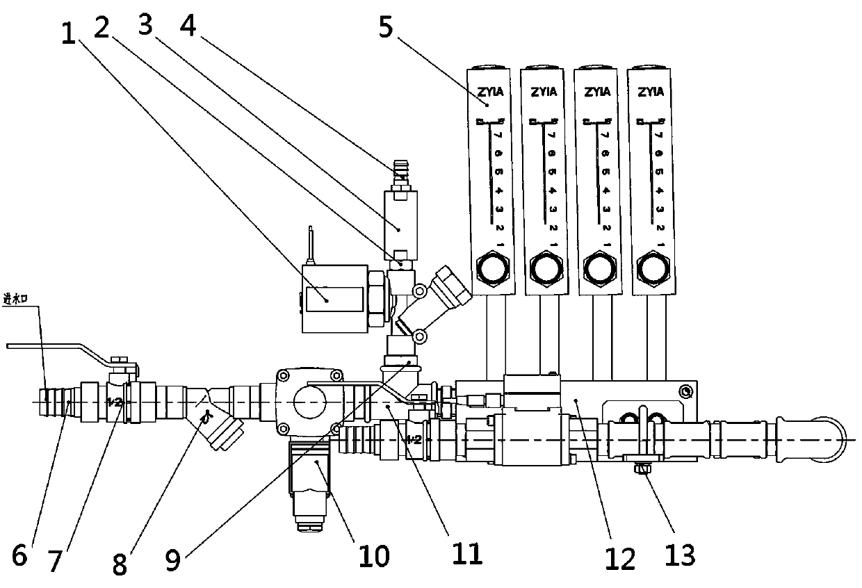
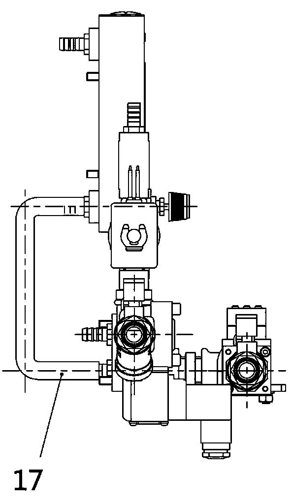
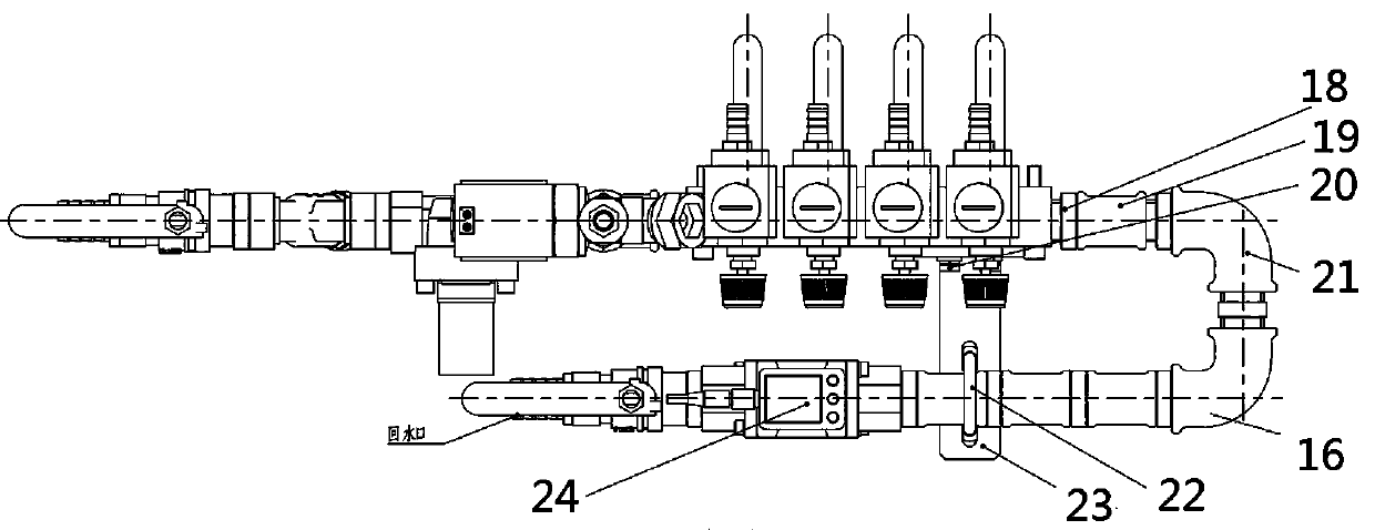
[0018] Please refer to the figure, in the embodiment of the present invention, a safe automatic drainage system includes a second straight-through tower joint 6, a four-point ball valve 7, a Y-shaped filter 8, a first straight-through pipe joint 9, and a pilot-operated two-way Solenoid valve 10, inner thread tee 11 and water diversion plate 12; the second straight-through tower joint 6 is connected to the cold water pipe to allow cooling water to enter, and the rear side of the second straight-through tower joint 6 is sequentially connected with a four-point ball valve 7. Pilot-operated two-way solenoid valve 10, inner thread three-way 11, water diversion plate 12, second straight-through pipe joint 18, outer joint 19, four-point inner tooth elbow joint 21, pipeline 16 and digital flow switch for water 24. The four-point ball valve 7 controls the on-off of the cooling water entering the second straight-through tower joint 6. The main function of the pilot-operated two-way solen...

Embodiment 2

[0023] On the basis of Example 1, a Y-shaped filter 8 is communicated between the four-point ball valve 7 and the inner thread tee 11 to filter the cooling water entering the second straight-through tower joint 6 to prevent impurities from entering To the cooling system, reduce internal impurities and ensure smooth cooling water.

[0024] The cooling water 6 enters, circulates and cools through the water distribution plate 12 according to each water channel, and then flows back into the pipeline 16 through the water distribution plate 12, and finally is discharged from the water outlet (the water is discharged from the rear side of the digital flow switch 24). When parts need to be replaced, the cooling water in the water channel needs to be discharged, the pilot two-way solenoid valve 10 closes the water channel, stops water intake, and the built-in filter Y-type direct-acting two-way solenoid valve 1 starts to work. At this time, the pipeline is opened, and the upper The gas...


PUM


Abstract

The invention relates to the field of waterway control, and particularly discloses a safe automatic drainage system which comprises a second straight-through tower-shaped joint, a quartering ball valve, a Y-shaped filter, a first straight-through pipe joint, a pilot-operated two-way electromagnetic valve, an internal thread tee joint and a water diversion board. The rear side of the second straight-through tower-shaped joint sequentially communicates with the quartering ball valve, the pilot-operated two-way electromagnetic valve, the internal thread tee joint, the water diversion board, the second straight-through pipe joint, an outer joint, a quartering internal tooth elbow joint, a pipeline and a digital flow switch for water; the other end of the internal thread tee joint communicateswith the first straight-through pipe joint, the upper end of the first straight-through pipe joint communicates with an internal joint, the upper end of the internal joint communicates with a one-wayvalve, and the other end of the one-way valve communicates with a first straight-through tower-shaped joint. The a safe automatic drainage system is applied to a device needing drainage in a water path, particularly when parts in the water path need to be replaced, the automatic drainage function is mainly achieved, operation is easy, and no residual water stain exists in the water path.

Description

technical field [0001] The invention relates to the field of waterway control, in particular to a safe automatic drainage system. Background technique [0002] With the rapid development of economy and technology, the market's demand for products has also been continuously upgraded, the functional requirements of mechanical products have increased, and mechanical automation has also achieved rapid development. In mechanical automation, it is often necessary to use cooling water to cool down the equipment so that the mechanical equipment can run safely and stably. However, if a part of the waterway in the cooling system is damaged or needs to be replaced, the main method is to directly remove the parts manually, but The cooling water in the waterway will spill out when the parts are removed, which will bring potential safety hazards and safety problems, which can no longer meet the needs of production. Therefore, it is necessary to improve the existing drainage system to solv...

Claims


Application Information

Patent Timeline
IPC IPC(8): E03B7/08
CPCE03B7/08
Inventor 邓亮桂亚平颜剑航许安权伍小龙
Owner GUANGZHOU SONGXING ELECTRIC
Features
  • R&D
  • Intellectual Property
  • Life Sciences
  • Materials
  • Tech Scout
  • Unparalleled Data Quality
  • Higher Quality Content
  • 60% Fewer Hallucinations
Learn More