A cable force real-time monitoring device and monitoring method

A real-time monitoring and cable force technology, which is applied in the field of bridge engineering and construction, can solve the problems of non-uniform strain changes of point-type strain sensors, difficulty in ensuring absolute centering of the force of the force measuring ring, and affecting the accuracy of cable force monitoring. Long-term weather resistance, unique anti-electromagnetic interference ability, stable monitoring results

Active Publication Date: 2021-03-16
HUBEI UNIV OF TECH
View PDF9 Cites 0 Cited by
  • Summary
  • Abstract
  • Description
  • Claims
  • Application Information

AI Technical Summary

Problems solved by technology

However, limited by cable length, installation space and location, the force measuring ring is usually a thick-walled ring structure, and the stress of each section is not uniformly distributed, but varies with height, and the slight deviation of the installation position of the point strain sensor may lead to large deviation in force measurement
At the same time, in the process of on-site installation and use, it is difficult to ensure the absolute centering of the force measuring ring, and there may be eccentric pressure, resulting in non-uniform changes in the local strain of the point strain sensor, which affects the accuracy of cable force monitoring

Method used


Image

  • A cable force real-time monitoring device and monitoring method
  • A cable force real-time monitoring device and monitoring method
  • A cable force real-time monitoring device and monitoring method

Examples


Embodiment Construction

[0033] The specific structure and implementation mode of the present invention will be further described below in conjunction with the accompanying drawings, but the protection scope of the present invention should not be limited thereby.

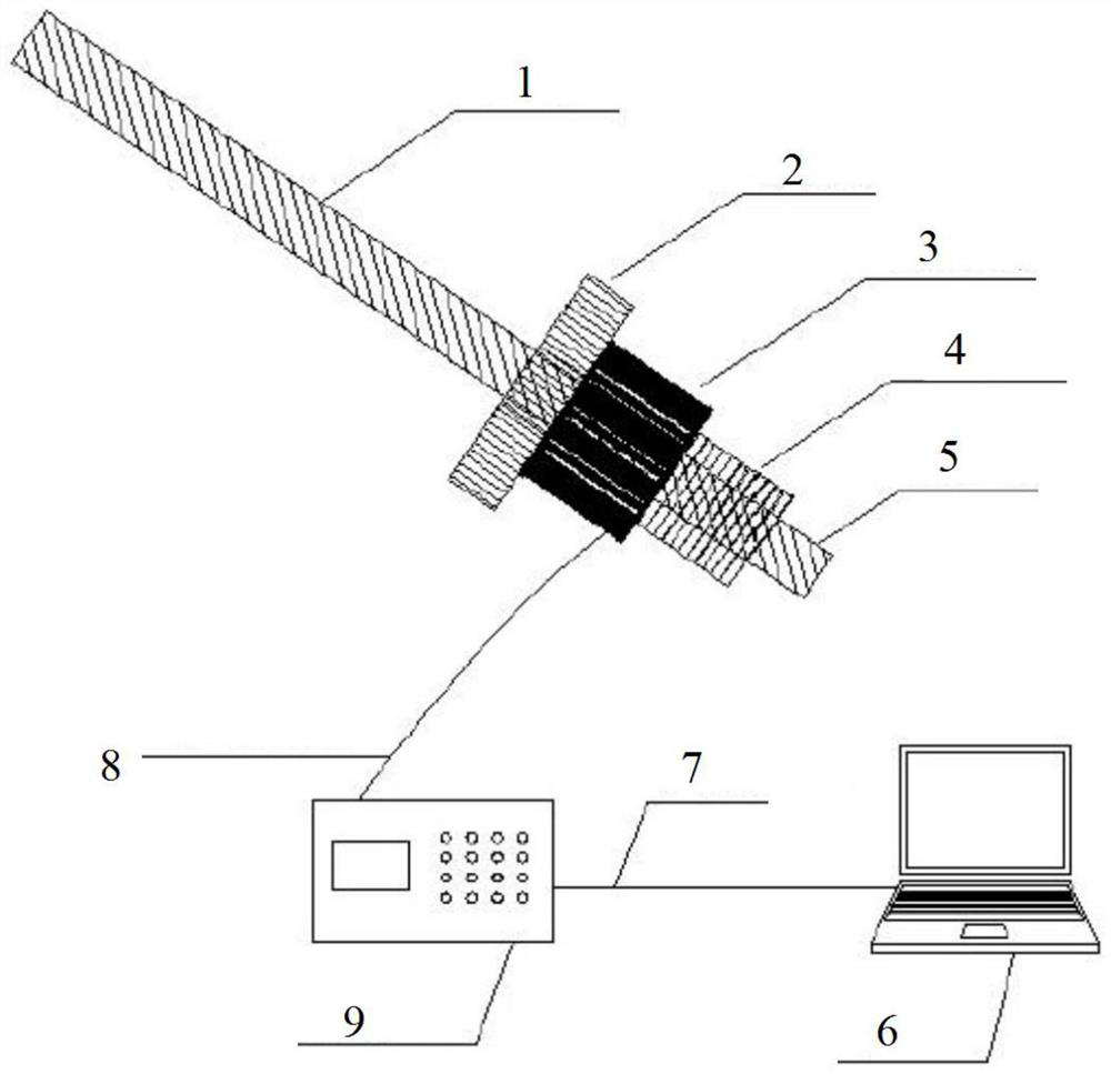
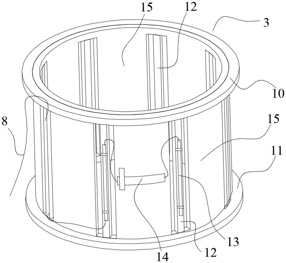
[0034] Such as figure 1 with figure 2As shown, a cable force real-time monitoring device includes a force-measuring ring 3 and eight long-gauge fiber grating strain sensors 13. The force-measuring ring 3 is a hollow ring, which includes a first force-bearing ring 10, a second Forced ring 11 and side wall 15 provide axial grooves on side wall 15 to form narrow columns 12 for installing sensors. In this embodiment, there are 8 narrow columns 12, and each narrow column 12 is installed One long-gauge fiber grating strain sensor 13 , generally more than four long-gauge fiber grating strain sensors 13 can obtain stable data. The long gauge fiber grating strain sensor 13 is firmly connected by cold light welding process, and measures the longit...


PUM


Abstract

The invention discloses a real-time monitoring device and monitoring method of a cable force. The monitoring device comprises a cage-structure force measurement ring, wherein a groove is formed in a side wall of the cage-structure force measurement ring, a plurality of long-gauge length fiber grating precision strain sensors are arranged at a middle part of the side wall of the force measurement ring, average strain of an intermediate segment of the intermediate ring within a certain range is measured, a fiber grating temperature sensor is arranged to compensate a temperature, the strain is converted to an optical signal by the fiber grating sensors, the optical signal is transmitted to a fiber grating demodulator for demodulation by an optical cable, and the optical signal is transmittedto a computer by a network cable. Load test is performed in a laboratory, average strain data acquired by the plurality of long-gauge length stress sensors is combined to perform least square fit analysis, and a relation curve of the pressure of the test ring and equivalent axis average strain is calibrated. The controller is used for analyzing real-time monitoring data of a force measurement ring, the cable force is solved, and automatic real-time monitoring of the cable force is achieved.

Description

technical field [0001] The invention belongs to the field of bridge engineering and construction, and relates to a cable force monitoring technology, in particular to a cable force real-time monitoring device and a monitoring method, which are used in cable-stayed bridge projects to monitor various types of cable-stayed bridges, suspension bridges, arch bridges, etc. Long-term real-time monitoring of the cable force of the cable and boom. Background technique [0002] Cables or suspenders are the main load-bearing components of cable-supported bridges. Real-time monitoring of their stress status and diagnosis of damage are of great significance to the safe operation of structures. At present, the existing cable force monitoring techniques are mainly divided into indirect method and direct method. The indirect method tests the physical parameters related to the tension of the cable, and then indirectly obtains the tension of the cable by using the correlation between the par...

Claims


Application Information

Patent Timeline
Patent Type & Authority Patents(China)
IPC IPC(8): G01L5/04G01L1/24
CPCG01L1/246G01L1/247G01L5/0033G01L5/047
Inventor 王超
Owner HUBEI UNIV OF TECH
Why Eureka
Try Eureka