Radial seepage instrument and operation method thereof
An operation method and flow meter technology, applied in the field of radial seepage meter, can solve the problems of inconvenient discharge of soil sample gas, uneven soil sample state, affecting test accuracy, etc.
- Summary
- Abstract
- Description
- Claims
- Application Information
AI Technical Summary
Problems solved by technology
Method used
Image
Examples
Embodiment 1
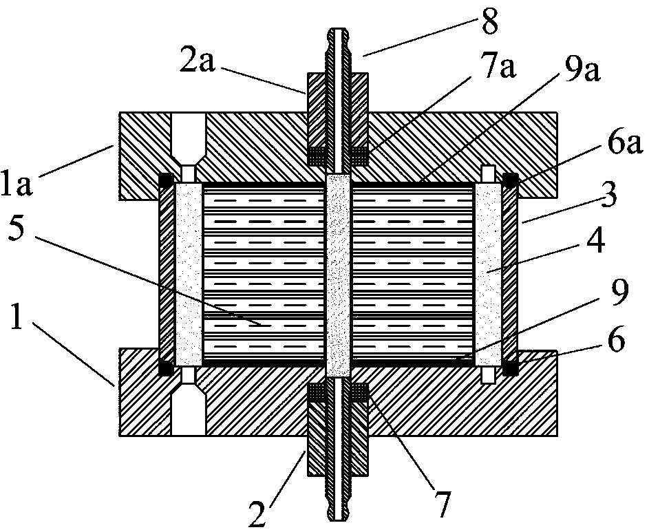
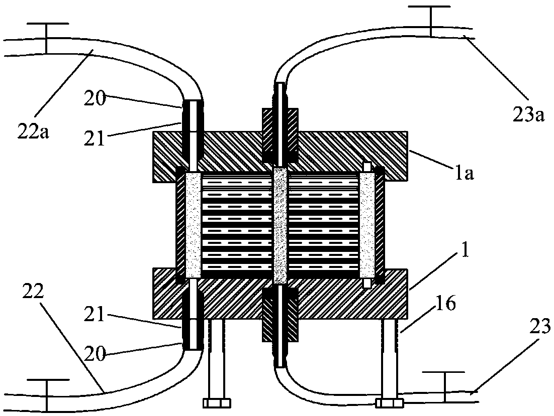
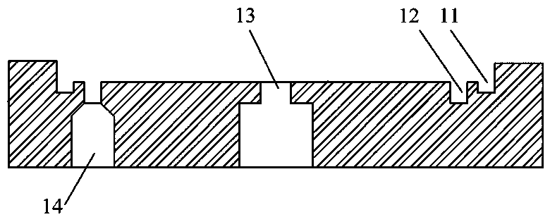
[0044] The schematic diagram of the main structure of this embodiment is shown in figure 1, for a complete structural schematic see figure 2 , Figure 3 to Figure 8 A schematic diagram of the main components. The main structure of the radial seepage meter mainly includes a water permeable cylinder 4, an outer sleeve 3, an upper cover 1a, a lower cover 1, and a water permeable rod 8; the soil sample 5 suitable for the radial seepage meter is circular and columnar, with a height of 40.0mm , the outer diameter is 61.8mm, the inner diameter is 6.18mm, and a permeable rod 8 is inserted in the central hole; The height of the permeable cylinder 4 is 42.0mm, the outer diameter is 74.8mm, and the inner diameter is 62.2mm; the height of the outer sleeve 3 is 42.0mm, the outer diameter is 81.8mm, and the thickness is 3.4mm. The upper gasket 9a and the lower gasket 9 are made of soft rubber, both of which are ring-shaped, with an inner diameter of 5.8mm, an outer diameter of 61.8mm, a...
Embodiment 2
[0055] The difference between this embodiment and Embodiment 1 is that the outer sleeve 3 and the water-permeable cylinder 4 are combined into a combination, see Figure 9 . The combination is achieved by applying 10.0 mm wide structural glue to both ends of the inner surface of the outer sleeve 3, bonding the outer sleeve 3 and the permeable sleeve 4 into one body, and the two ends are flush. Correspondingly, the experimental operation method is basically the same as that of Example 1, except that the second step is changed to:
[0056] Step 2-2: Place the filter paper inside the combination of the outer sleeve 3 and the water-permeable tube 4, push the soil sample 5 in, place the combination and the soil sample 5 on the lower cover 1, and open the hole in the center of the soil sample 5 Place the filter paper inside, and place the upper gasket 9a in the center.
Embodiment 3
[0058] The difference between this embodiment and embodiment 1 is that the outer sleeve 3 and the lower cover 1 are integrally manufactured, and the schematic diagram of the assembly is shown in Figure 10 . This saves the making of the sealing ring groove 11 in the lower cover 1, and saves the lower sealing ring 6, which facilitates the operation. Correspondingly, the experimental operation method is basically the same as in Example 1, except that the first two steps are changed to:
[0059] Step 3-1: Adjust the feet 16 of the lower cover 1 so that the lower cover 1 is in a horizontal state; place the lower gasket 9 in the center;
[0060] Step 3-2: Place the filter paper inside the permeable cylinder 4, push the soil sample 5 into the permeable cylinder 4, put them into the outer sleeve 3 together, place the filter paper in the hole in the center of the soil sample 5, and place the upper gasket 9a in the center .
PUM
| Property | Measurement | Unit |
|---|---|---|
| Outer diameter | aaaaa | aaaaa |
| Thickness | aaaaa | aaaaa |
| The inside diameter of | aaaaa | aaaaa |
Abstract
Description
Claims
Application Information
 - R&D
- Intellectual Property
- Life Sciences
- Materials
- Tech Scout
- Unparalleled Data Quality
- Higher Quality Content
- 60% Fewer Hallucinations
Browse by: Latest US Patents, China's latest patents, Technical Efficacy Thesaurus, Application Domain, Technology Topic, Popular Technical Reports.
© 2025 PatSnap. All rights reserved.Legal|Privacy policy|Modern Slavery Act Transparency Statement|Sitemap|About US| Contact US: help@patsnap.com


