Method for determining water collection area threshold value during digital river network extraction

A water catchment area and determination method technology, applied in water resources assessment, image data processing, character and pattern recognition, etc., can solve the problem of inability to perfectly distinguish between water bodies and other ground objects, model algorithms cannot identify any ground objects, and water body recognition As a result, problems such as discontinuity in the main stream have achieved the effect of facilitating automatic generation, stable and reliable data sources, and promoting in-depth development

Active Publication Date: 2019-08-02
HOHAI UNIV
View PDF3 Cites 2 Cited by
  • Summary
  • Abstract
  • Description
  • Claims
  • Application Information

AI Technical Summary

Problems solved by technology

Theoretically speaking, the water body identification result of remote sensing image data is a digital reflection of the real water body, but because the model algorithm for water area extraction based on remote sensing image research cannot identify any ground object, nor can it perfectly distinguish water bodies from other land objects, and because The remote sensing image data itself has errors due to cloud cover images, or there are small water bodies in the basin itself. The water body identification results are discontinuous in the main stream and scattered in the tributaries. It is impossible to directly extract the basin water system from the remote sensing image water body identification results.

Method used


Image

  • Method for determining water collection area threshold value during digital river network extraction
  • Method for determining water collection area threshold value during digital river network extraction
  • Method for determining water collection area threshold value during digital river network extraction

Examples


Embodiment Construction

[0049] In order to make the object, technical solution and advantages of the present invention clearer, the present invention will be described in detail below with reference to the accompanying drawings and specific embodiments.

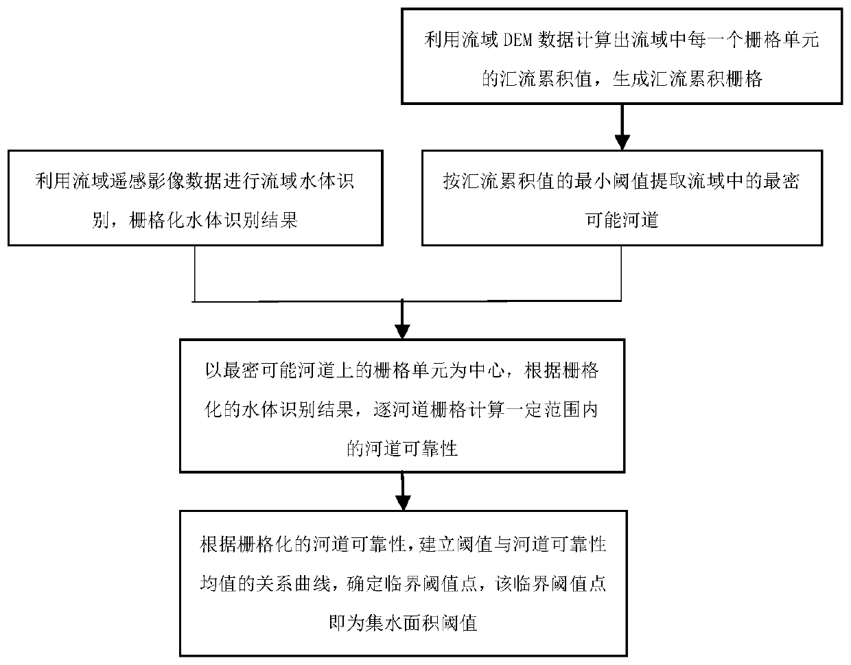
[0050] Such as figure 1 As shown, a method for determining the catchment area threshold when a digital river network is extracted in the present invention comprises the following steps:

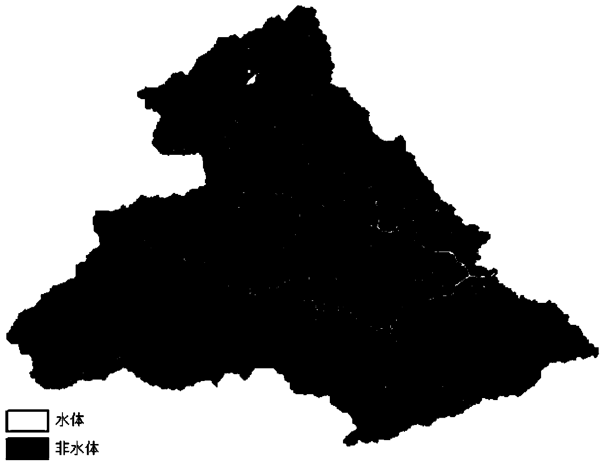
[0051] S1. Use the remote sensing image data of the watershed to identify the water body in the watershed, and rasterize the water body identification results (such as figure 2 ), including the following steps:

[0052]Using the spectral characteristics of different surface objects, the water body index calculation method based on remote sensing images is used to obtain the rasterized water body recognition results, and the grids identified as water bodies are marked to generate water body grids.

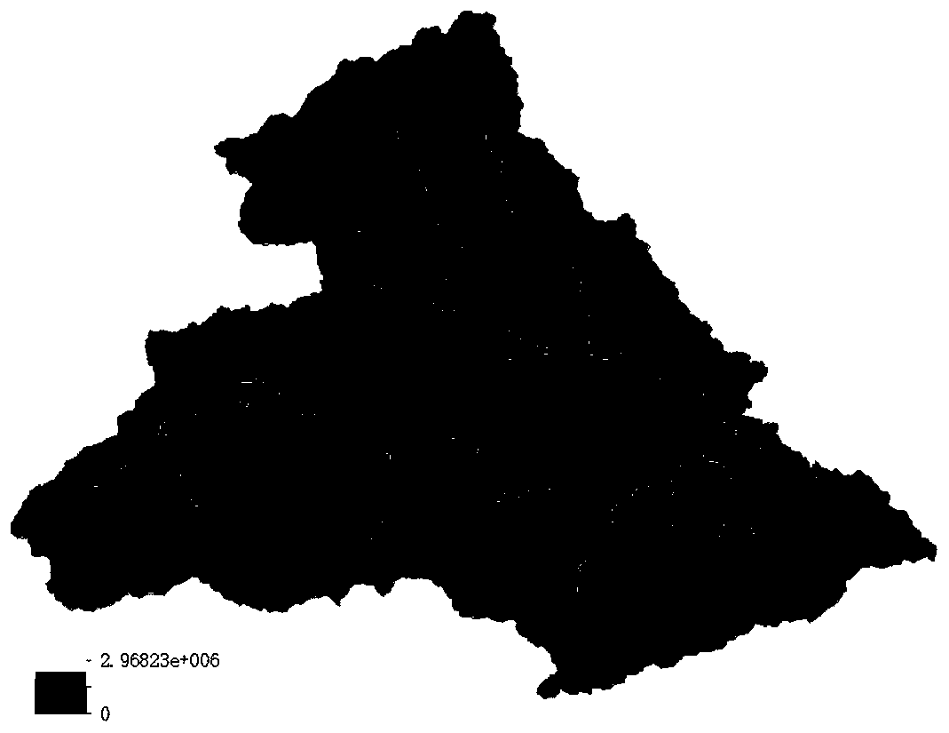
[0053] S2. Use the DEM data of the watershed to calculate the cu...


PUM


Abstract

The invention discloses a method for determining a water collection area threshold value during digital river network extraction, and the method comprises the steps: carrying out the recognition of awatershed water body through watershed remote sensing image data, and carrying out the rasterization of a water body recognition result; calculating a confluence accumulation value of each grid unit in the drainage basin by utilizing the watershed DEM data, and generating a confluence accumulation grid; extracting the closest possible river channel in the river basin according to the minimum threshold value of the confluence accumulation value; calculating the river channel reliability within a certain range one by one by taking the grid unit on the closest possible river channel as a center according to the rasterized water body recognition result; and according to the rasterized river channel reliability, establishing a relation curve of a threshold value and a river channel reliabilitymean value, and determining a critical threshold value point which is a water collection area threshold value. The method has the advantages of being stable and reliable in data source, high in calculation efficiency, objective and reasonable in result and the like, and facilitates determination of a basin water collection area threshold value and extraction of a digital river network.

Description

technical field [0001] The invention relates to the technical field of hydrology, in particular to a method for determining the catchment area threshold value during digital river network extraction. Background technique [0002] The characteristics of the river network reflect the comprehensive hydrological characteristics of the watershed. With the development of technologies such as remote sensing, geographic information, and digital watersheds, the distributed hydrological model based on the grid digital elevation model (DEM, Digital Elevation Model) has become an important model for its full consideration of the spatial variation of rainfall and underlying surface conditions. Trends in watershed hydrological modeling. The accurate extraction of the river network provides guarantee for the model calculation. In order to further promote the development of the hydrological model of the watershed, it is necessary to further study the determination method of the catchment a...

Claims


Application Information

Patent Timeline
IPC IPC(8): G06T7/62G06K9/00
CPCG06T7/62G06T2207/10032G06T2207/30184G06V20/182Y02A90/30
Inventor 徐杰马亚楠李致家
Owner HOHAI UNIV
Why Eureka
Try Eureka