Determination method of optimal lane and vehicle control system

A determination method and lane technology, applied to the determination method of the optimal lane and the field of vehicle control system, can solve the problem that the driver cannot determine the optimal lane in advance and cannot be arranged in the lane

Inactive Publication Date: 2019-08-02
GUANGZHOU XIAOPENG MOTORS TECH CO LTD
View PDF4 Cites 6 Cited by
  • Summary
  • Abstract
  • Description
  • Claims
  • Application Information

AI Technical Summary

Problems solved by technology

[0003] In practice, it is found that due to the limitation of visual distance, drivers are often unable to determine the optimal lane in advance, resulting in not being able to queue in the lane that can make them reach their destination the fastest

Method used


Image

  • Determination method of optimal lane and vehicle control system
  • Determination method of optimal lane and vehicle control system
  • Determination method of optimal lane and vehicle control system

Examples


Embodiment 1

[0100] see figure 1 , figure 1 It is a schematic flowchart of a method for determining an optimal lane disclosed in an embodiment of the present invention. like figure 1 As shown, the method may include the following steps.

[0101] 101. The vehicle control system acquires the driving direction corresponding to each lane of a certain intersection that the vehicle is about to pass through and the waiting time for a red light corresponding to each lane.

[0102] In the embodiment of the present invention, the driving direction can be obtained through the camera module and / or the intersection traffic sign provided by the V2I facility, and the red light waiting time can be obtained through the cloud map and / or the traffic light information provided by the V2I facility, which is not limited in the embodiment of the present invention . Among them, the V2I facility can be a facility set up in each lane and capable of communicating with vehicles on each lane, such as traffic light...

Embodiment 2

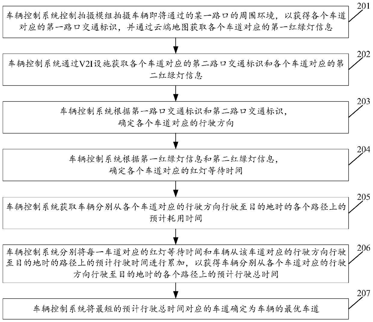
[0132] see figure 2 , figure 2 is a schematic flowchart of another optimal lane determination method disclosed in the embodiment of the present invention. like figure 2 As shown, the method may include the following steps.

[0133] 201. The vehicle control system controls the photographing module to photograph the surrounding environment of a certain intersection that the vehicle is about to pass, so as to obtain the first intersection traffic sign corresponding to each lane, and obtain the first traffic light information corresponding to each lane through the cloud map.

[0134] In the embodiment of the present invention, the surrounding environment may be the road surface of each lane, or may be a signboard corresponding to each lane, which is not limited in this embodiment of the present invention.

[0135] In the embodiment of the present invention, the first intersection traffic sign corresponding to each lane at least includes any one of straight ahead, left turn, ri...

Embodiment 3

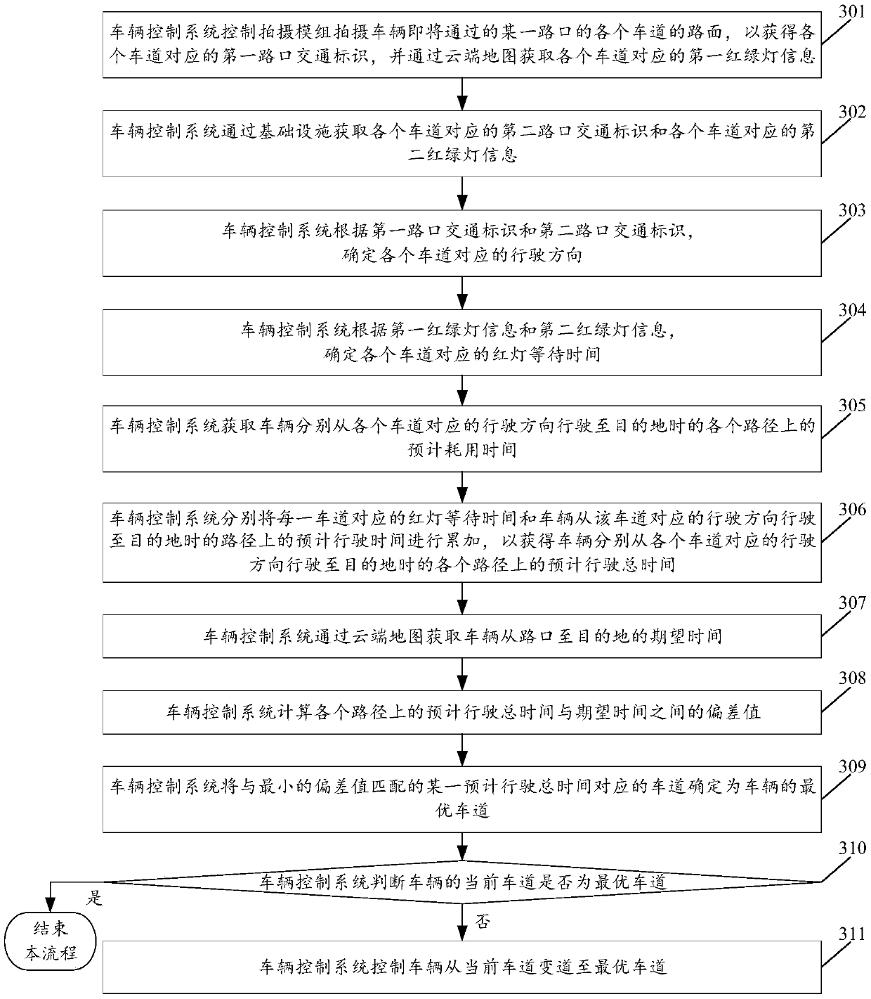
[0169] see image 3 , image 3 It is a schematic flowchart of another method for determining an optimal lane disclosed in an embodiment of the present invention. like image 3 As shown, the method may include the following steps.

[0170] 301-306; where, Step 301-Step 306 is the same as Step 201-Step 206 in Embodiment 2, and will not be repeated here.

[0171] 307. The vehicle control system obtains the expected time of the vehicle from the intersection to the destination through the cloud map.

[0172] In the embodiment of the present invention, the expected time is the time required for the vehicle to travel from the intersection to the destination obtained from the cloud map.

[0173] 308. The vehicle control system calculates the deviation value between the estimated total time and the expected time on each route.

[0174] 309. The vehicle control system determines the lane corresponding to a certain estimated total time that matches the smallest deviation value as th...


PUM


Abstract

The embodiments of the invention relate to the vehicle intelligent auxiliary driving technology field and disclose a determination method of an optimal lane and a vehicle control system. The method comprises the following steps of obtaining a running direction corresponding to each lane of one intersection which a vehicle is about to pass and red light waiting time corresponding to each lane; acquiring estimated consumed time on each path when the vehicle runs to a destination from a running direction corresponding to each lane, wherein the estimated consumed time at least includes estimated running time of the vehicle and other waiting time on each path except for the red light waiting time corresponding to each lane; obtaining estimated total time on each path when the vehicle runs to the destination from the running direction corresponding to each lane according to the red light waiting time corresponding to each lane and the estimated consumed time on each path; and determining thelane corresponding to the shortest estimated total time to be the optimal lane of the vehicle. The fastest lane to get to the destination can be determined and the running time can be saved.

Description

technical field [0001] The invention relates to the technical field of vehicle intelligent assisted driving, in particular to a method for determining an optimal lane and a vehicle control system. Background technique [0002] With the development of the economy, the penetration rate of cars is getting higher and higher, and people rely more and more on cars as a means of transportation, which makes more and more cars on the road, especially during the peak period of travel concentration, the increase of cars on the road is even more serious Road congestion, such as road congestion caused by queuing at traffic intersections. In order to determine the lane that can make you reach your destination the fastest, currently you mainly rely on the driver in the car to judge the road conditions to get the rough traffic information of each lane when you are about to pass a certain intersection, and then drive the car to the driver's best. Excellent driveway. [0003] In practice, i...

Claims


Application Information

Patent Timeline
IPC IPC(8): G08G1/0962G05D1/02
CPCG05D1/0253G05D1/0214G05D1/028G05D1/0276G08G1/09623
Inventor 徐现昭
Owner GUANGZHOU XIAOPENG MOTORS TECH CO LTD
Why Eureka
Try Eureka