Panoramic tunnel video monitoring device and method

A video surveillance and panoramic technology, applied in the field of highway tunnel operation and management, can solve the problems of not being able to display all scenes, not being able to splicing and displaying camera images, and poor continuity of monitoring screen content

Inactive Publication Date: 2019-08-02
招商局重庆公路工程检测中心有限公司
View PDF9 Cites 8 Cited by
  • Summary
  • Abstract
  • Description
  • Claims
  • Application Information

AI Technical Summary

Problems solved by technology

[0005] First, when there are many cameras in the tunnel, only the real-time images of some of the cameras can be displayed on the monitor, and the display of all the camera images needs to be switched manually one by one or automatically at regular intervals. displayed intuitively;
[0006] Second, even if the monitor can display all the camera images at the same time, the displayed pictures are isolated scene images one by one. Since the image scenes have not been fused, the content of the monitoring picture has poor coherence and low intelligibility, which is not convenient for monitoring Personnel quickly discover and track abnormal conditions in the tunnel;
[0007] Third, limited by the layout and installation methods of cameras in the tunnel, the current image processing technology cannot quickly and accurately stitch and display the images of each camera

Method used


Image

  • Panoramic tunnel video monitoring device and method
  • Panoramic tunnel video monitoring device and method
  • Panoramic tunnel video monitoring device and method

Examples


Embodiment Construction

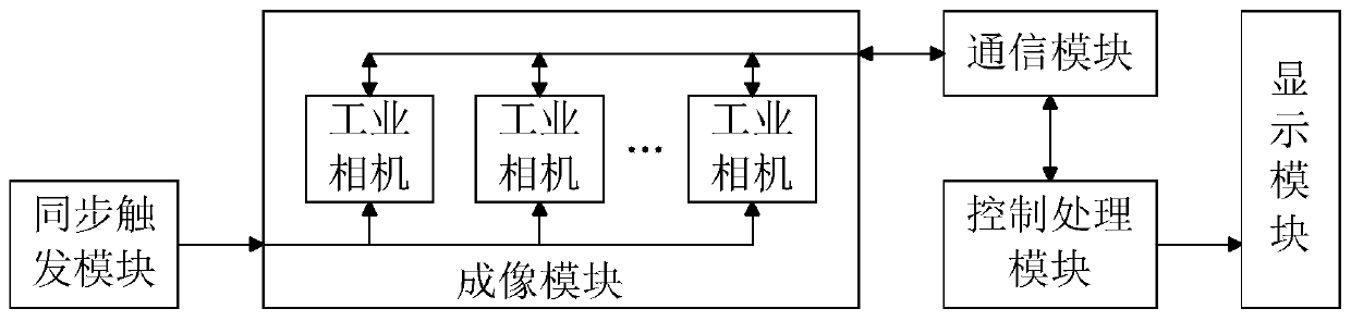
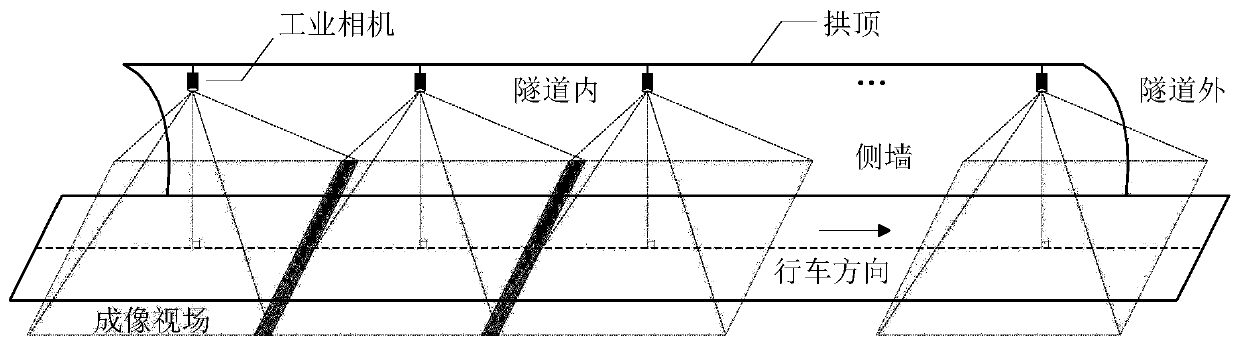
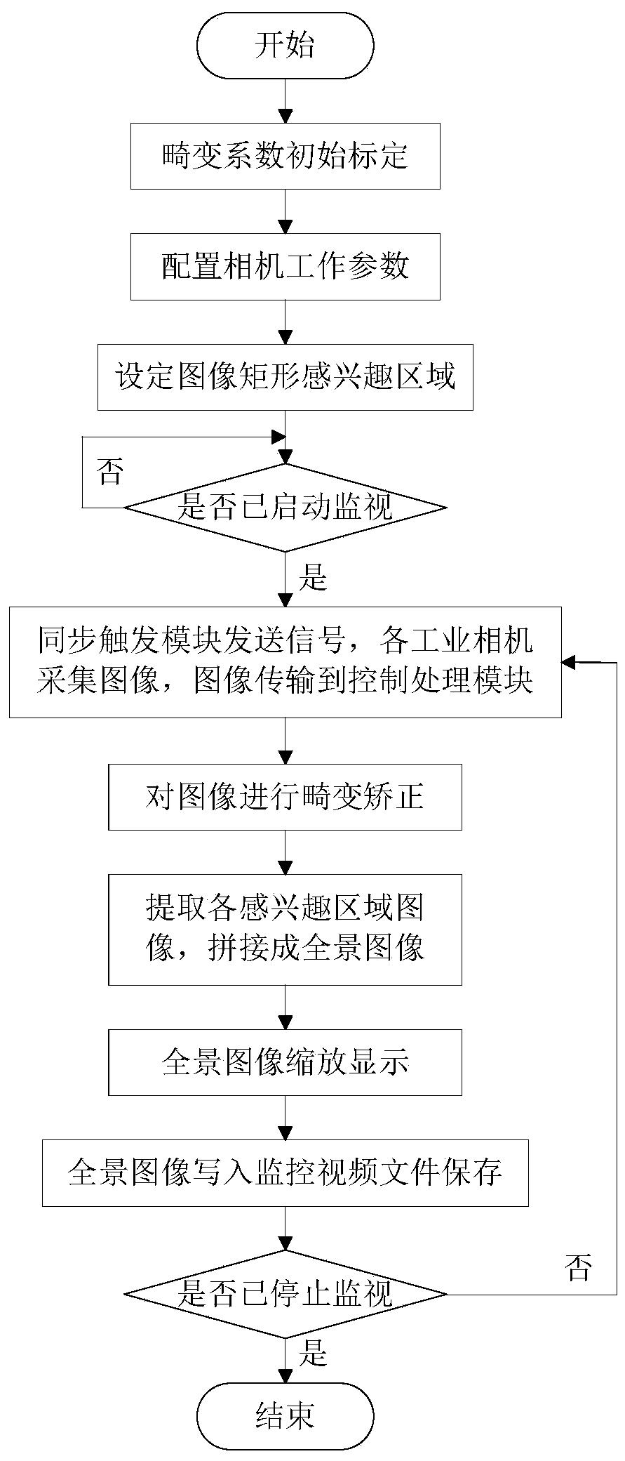
[0049]Embodiments of the present invention are described below through specific examples, and those skilled in the art can easily understand other advantages and effects of the present invention from the content disclosed in this specification. The present invention can also be implemented or applied through other different specific implementation modes, and various modifications or changes can be made to the details in this specification based on different viewpoints and applications without departing from the spirit of the present invention. It should be noted that the diagrams provided in the following embodiments are only schematically illustrating the basic concept of the present invention, and the following embodiments and the features in the embodiments can be combined with each other in the case of no conflict.

[0050] Wherein, the accompanying drawings are for illustrative purposes only, and represent only schematic diagrams, rather than physical drawings, and should ...


PUM


Abstract

The invention relates to a panoramic tunnel video monitoring device which comprises an imaging module, a synchronous triggering module, a communication module, a control processing module and a display module. The imaging module comprises a plurality of industrial cameras arranged near the tunnel vault along the driving direction and is used for continuously collecting the top view images of eachdivided interval in the tunnel; the synchronous trigger module comprises a signal generator and a signal distributor, and is used for generating a specific acquisition control signal and sending the specific acquisition control signal to each industrial camera; the communication module is connected with the imaging module and the control processing module and is used for realizing the real-time transmission of the camera configuration parameters and the acquired image data; the control processing module comprises a processor, a video image input interface, a video image output interface and amemory and is used for the imaging module configuration control and the video image receiving, panoramic splicing and storage; and the display module is connected with the video image output interfaceof the control processing module and is used for displaying the panoramic video monitoring image in the tunnel.

Description

technical field [0001] The invention belongs to highway tunnel operation management technology, in particular to a panoramic tunnel video monitoring device and method. Background technique [0002] Tunnels are special road sections for highway operation and management, and the incidence of traffic accidents and the severity of accident consequences are significantly higher than ordinary road sections. As the main sub-item facility of highway tunnel electromechanical equipment, the video surveillance system is of great significance in ensuring tunnel operation safety and emergency response to accidents. [0003] Existing highway tunnel video monitoring system generally is made of video camera, communication equipment, hard disk video recorder and monitor. Among them, the camera is installed along the inner wall of the tunnel, and the optical axis of the lens intersects with the driving direction at an acute angle to collect video images of the road section in front of the ca...

Claims


Application Information

Patent Timeline
Patent Type & Authority Applications(China)
IPC IPC(8): H04N7/18H04N5/232H04N5/262H04N5/265H04N5/04H04N5/247
CPCH04N7/181H04N5/2624H04N5/265H04N5/2628H04N5/04H04N23/66H04N23/80H04N23/698H04N23/90
Inventor 代东林邹小春郭兴隆袁源庞荣苏宇峰韩坤林李响蒋明星邱进邱林韩拓
Owner 招商局重庆公路工程检测中心有限公司
Why Eureka
Try Eureka