Machining method of spiral baffle plate pipe holes

A technology of spiral baffles and processing methods, which can be applied to metal processing equipment, manufacturing tools, welding equipment, etc., and can solve problems such as inability to realize openings

Active Publication Date: 2019-08-06
WUHAN GUOKONG SCI & TECH CO LTD
View PDF9 Cites 6 Cited by
  • Summary
  • Abstract
  • Description
  • Claims
  • Application Information

AI Technical Summary

Problems solved by technology

For discontinuous spiral baffles, although the baffles are flat, there is a certain angle between the normal line of the pipe hole and the axis, so the opening direction must also form a corresponding angle with the plate surface; for continuous spiral baf

Method used


Image

  • Machining method of spiral baffle plate pipe holes

Examples


Embodiment Construction

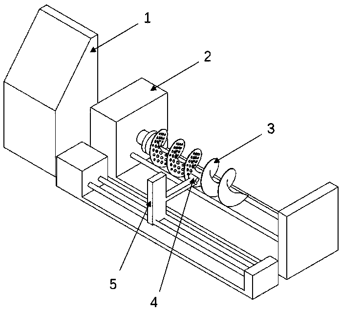
[0005] Install the spiral baffle that needs to be drilled on the rotary drive device with tooling, and make a good support, adjust the rotation fluctuation of the spiral baffle, input the control data that needs to be processed into the control system, and debug the rotary drive, spiral baffle, etc. The parameters of flow plate, hole opening device and positioning device, the control system controls the rotary drive device to rotate the spiral baffle to the angle to be processed, the control system controls the support and positioning device to make the hole opening device reach the predetermined processing position, and is controlled by the control system The lower support positioning device cooperates with the opening device to complete the processing of a pipe hole. Then the control system controls the rotary drive device to rotate the spiral baffle, and at the same time the control system controls the support positioning device to make the hole opening device reach the pred...


PUM


Abstract

The invention provides a machining method of spiral baffle plate pipe holes. The machining method is characterized by comprising a control system, a rotary driving device, a spiral baffle plate, and ahole opening device and a support positioning device; and machining of the spiral baffle plate does not need to be matched with a pipe plate, and machining of all the pipe holes is completed intelligently by the control system. According to the machining method of the spiral baffle plate pipe holes, the hole opening position is accurately positioned through an intelligent manufacturing technology, the hole opening device is used for opening holes, and continuous curved surface hole opening technology is realized.

Description

technical field [0001] The invention relates to a processing method for a tube hole of a spiral baffle, belonging to the field of intelligent manufacturing. Background technique [0002] Baffles are the most commonly used baffles in shell-and-tube heat exchangers. The commonly used structures are bow-shaped, ring-shaped, and circular. They are all flat-plate structure baffles. A shell-and-tube heat exchanger may Several to dozens of baffles are used. Because the baffles need to pass through the heat exchange tubes, the position of each tube hole on the baffles is extremely demanding. The most conventional processing method is multiple baffles and tube sheets. With drill. When the shell-and-tube heat exchanger uses a flat structure baffle, there are defects such as large pressure drop, flow stagnation zone, easy scaling, and low heat transfer efficiency on the shell side. Over the years, engineers and technicians have been exploring various efficient structures, among which...

Claims


Application Information

Patent Timeline
IPC IPC(8): B23K26/382B23K26/70
CPCB23K26/382B23K26/702
Inventor 唐柳华李龙张余祥张荣
Owner WUHAN GUOKONG SCI & TECH CO LTD
Why Eureka
Try Eureka