
Laser welding clamp and welding method

A technology of laser welding jig and welding method, which is applied in the direction of laser welding equipment, welding equipment, welding equipment, etc., which can solve the problems of welding penetration, perforation, failure to guarantee material quality, and failure of normal use of materials, so as to achieve the effect of ensuring quality

Inactive Publication Date: 2019-08-06
深圳力星激光智能装备有限公司
View PDF13 Cites 5 Cited by
  • Summary
  • Abstract
  • Description
  • Claims
  • Application Information

AI Technical Summary

Problems solved by technology

[0003] Due to the strong penetrability of laser welding, when welding thinner materials, it is easy to have bad phenomena such as welding through and perforation, which leads to the failure of normal use of the welded materials
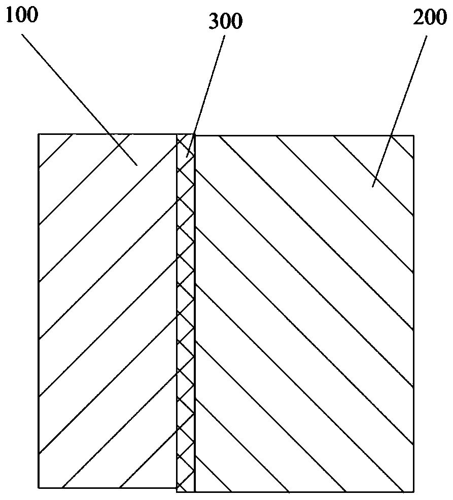
In the prior art, welding is usually performed on thinner materials of the opposite sex, such as welding stainless steel and nickel-copper together. Due to the large differences in the metal structure and melting point of the materials of the opposite sex, the thinner materials of the opposite sex are welded together. During welding, it is usually easy to have poor fit and gaps at the joint position, and the quality of the welded material cannot be guaranteed

Method used


Image

  • Laser welding clamp and welding method
  • Laser welding clamp and welding method
  • Laser welding clamp and welding method

Examples


Embodiment Construction

[0046] The present invention will be further described in detail below in conjunction with the accompanying drawings and embodiments. It should be understood that the specific embodiments described here are only used to explain the present invention, but not to limit the present invention. In addition, it should be noted that, for the convenience of description, only some structures related to the present invention are shown in the drawings but not all structures.

[0047] In the description of the present invention, unless otherwise clearly specified and limited, the terms "connected", "connected" and "fixed" should be understood in a broad sense, for example, it can be a fixed connection, a detachable connection, or an integrated ; It can be a mechanical connection or an electrical connection; it can be a direct connection or an indirect connection through an intermediary, and it can be the internal communication of two components or the interaction relationship between two ...


PUM


Abstract

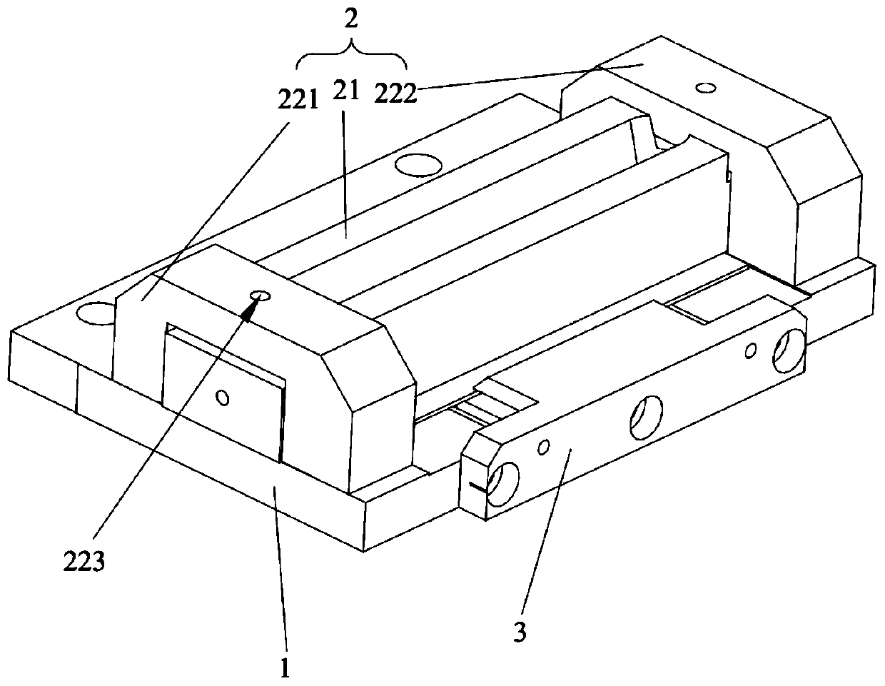
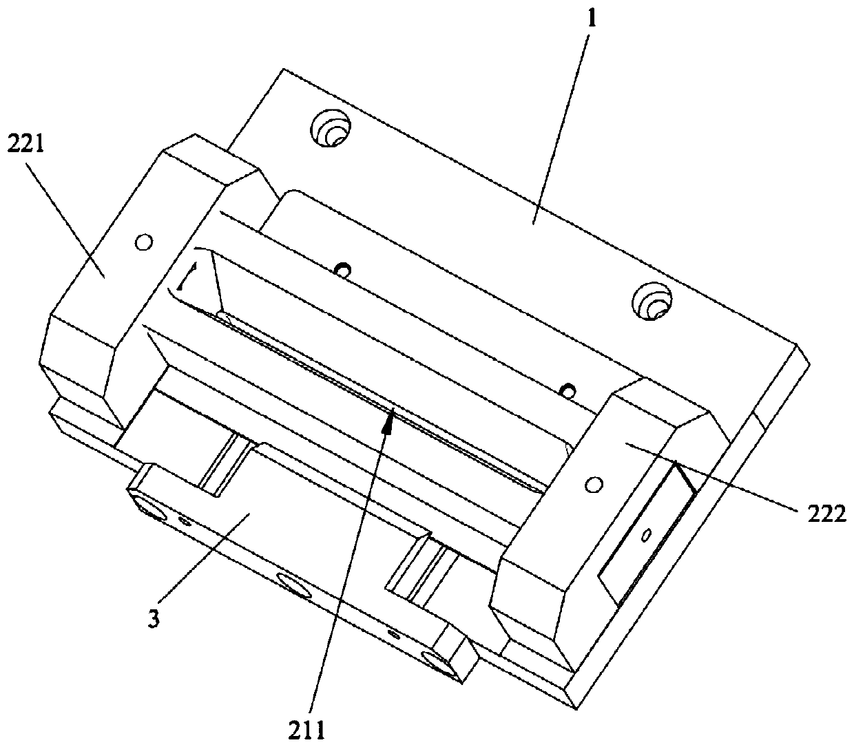
The invention relates to the technical field of laser welding, and discloses a laser welding clamp and a welding method. The laser welding clamp comprises a bottom plate, a pressing unit and a clamping unit, the pressing unit is used for pressing a workpiece on the bottom plate, the pressing unit comprises a pressing block, the pressing block is configured to be capable of moving relative to the bottom plate, so as to compress or get away from the workpiece, a welding groove is formed in the pressing block and is used for welding a joint on the workpiece, and the clamping unit comprises a first clamping part and a second clamping part which are arranged on the bottom plate and used for clamping the workpiece in a plane parallel to the bottom plate. By arranging the bottom plate and the pressing unit, the pressing unit is used for pressing the workpiece on the bottom plate so as to limit the position of the workpiece in the direction perpendicular to the bottom plate; the clamping unitis arranged, the clamping unit is used for clamping the workpiece in a plane parallel to the bottom plate so as to limit the position of the workpiece in the direction parallel to the bottom plate, then the joint of the workpiece is completely attached, no gap exists, and the quality of the welded workpiece is ensured.

Description

technical field [0001] The invention relates to the technical field of laser welding, in particular to a laser welding jig and a welding method. Background technique [0002] Laser welding is an efficient and precise welding method that uses a high-energy-density laser beam as a heat source. Laser welding is mainly used for welding thin-walled materials and low-speed welding. The welding process belongs to the heat conduction type, that is, the laser radiation heats the surface of the workpiece, and the surface heat diffuses to the inside through heat conduction. By controlling the width of the laser pulse, single point energy, peak power and repetition frequency and other parameters to melt the workpiece and form a specific molten pool. [0003] Due to the strong penetrability of laser welding, when welding thinner materials, it is easy to have bad phenomena such as welding through and perforation, which makes the welded materials unable to be used normally. In the prior ...

Claims


Application Information

Patent Timeline
IPC IPC(8): B23K26/70B23K26/21B23K37/04
CPCB23K26/21B23K26/702B23K37/0408B23K2101/185
Inventor 姚玉东穆雪彦尹德生刘毅田剑孙毅黎万颂赵聪聪郭栋
Owner 深圳力星激光智能装备有限公司
Learn More