Magnetic conductive pad for magnetic template

A template and magnetic conduction technology, which is applied in the field of magnetic conduction pads, can solve the problems of bumping into the magnetic template, grinding the magnetic template, damage to the magnetic template, etc., and achieves the effects of convenient maintenance, low cost and extended life

Pending Publication Date: 2019-08-06
宁波海迈克精密机械制造有限公司
View PDF0 Cites 0 Cited by
  • Summary
  • Abstract
  • Description
  • Claims
  • Application Information

AI Technical Summary

Problems solved by technology

However, due to the particularity of the grinding machine equipment, the installation of the magnetic template in the grinding machine basically covers the entire work surface of the grinding machine, and the workpiece is directly adsorbed on the surface of the magnetic template for processing during work. However, such a working method has the following problems: 1. ) Since the workpiece is in direct contact with the magnetic template, it is inevitable that it will bump into the magnetic template during multiple clamping projects, which will cause local high points on the surface of the magnetic template. It is necessary to give priority to grinding the high points in the next use. Avoid affecting the flatness of the magnetic template; 2) When encountering a workpiece that needs to grind the entire side end surface, such as a guide rail, since the guide rail is in direct contact with the magnetic template, it cannot be ground to the end at one time, otherwise the magnetic template will be ground. The magnetic template causes inevitable damage; 3) The grinding machine with the magnetic template needs to grind the plane of the magnetic template every year to ensure the overall flatness and the accuracy of the grinder. Therefore, the magnetic template will reduce part of the thickness and life of the grinder with each maintenance of the grinder. will also reduce

Method used


Image

  • Magnetic conductive pad for magnetic template
  • Magnetic conductive pad for magnetic template
  • Magnetic conductive pad for magnetic template

Examples


Embodiment 1

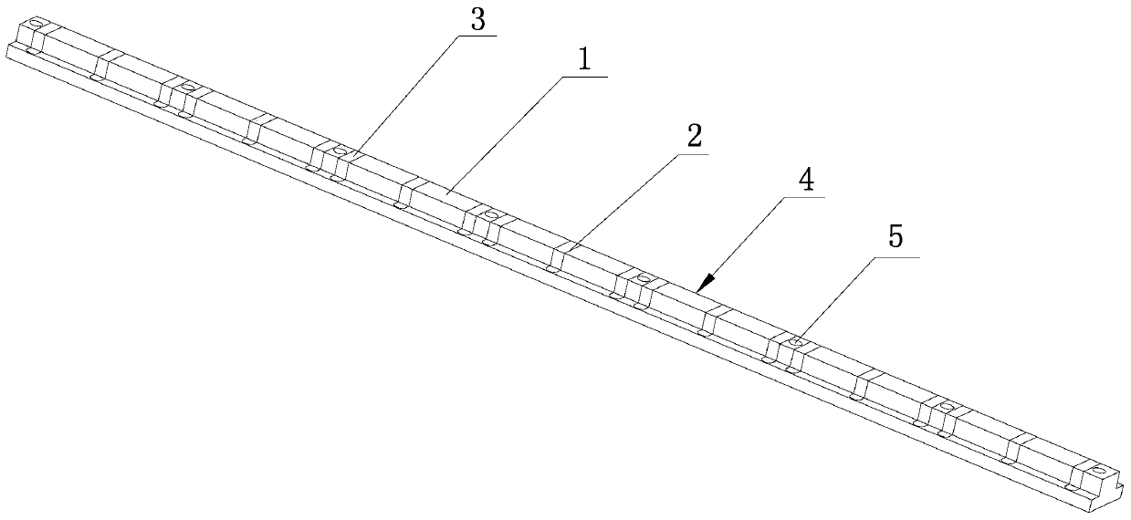
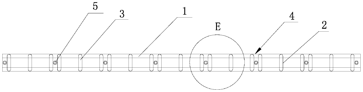
[0029] A magnetic pad suitable for a magnetic template proposed in this embodiment includes a magnetic conductor 1 whose longitudinal length is adapted to the magnetic template 8 and whose transverse section is in a "convex" shape. Generally, the longitudinal length of the magnetic conductor 1 is It can be designed so that its two ends are located outside the outermost magnetic pole 81 of the magnetic template 8, which is used as a fixed point for fixing the magnetic conductor 1 and the magnetic template 8, and the magnetic conductor 1 corresponds to each resin layer 82 on the magnetic template 8 A through-hole 2 that runs through the top and bottom and has hole walls on both sides is opened in the horizontal direction at the position. The through-hole 2 is poured with a non-magnetic material and forms a non-magnetic body 3 after the non-magnetic material is completely hardened. The non-magnetic body 3 The outer surface is flush with the outer surface of the magnetizer 1, and t...

Embodiment 2

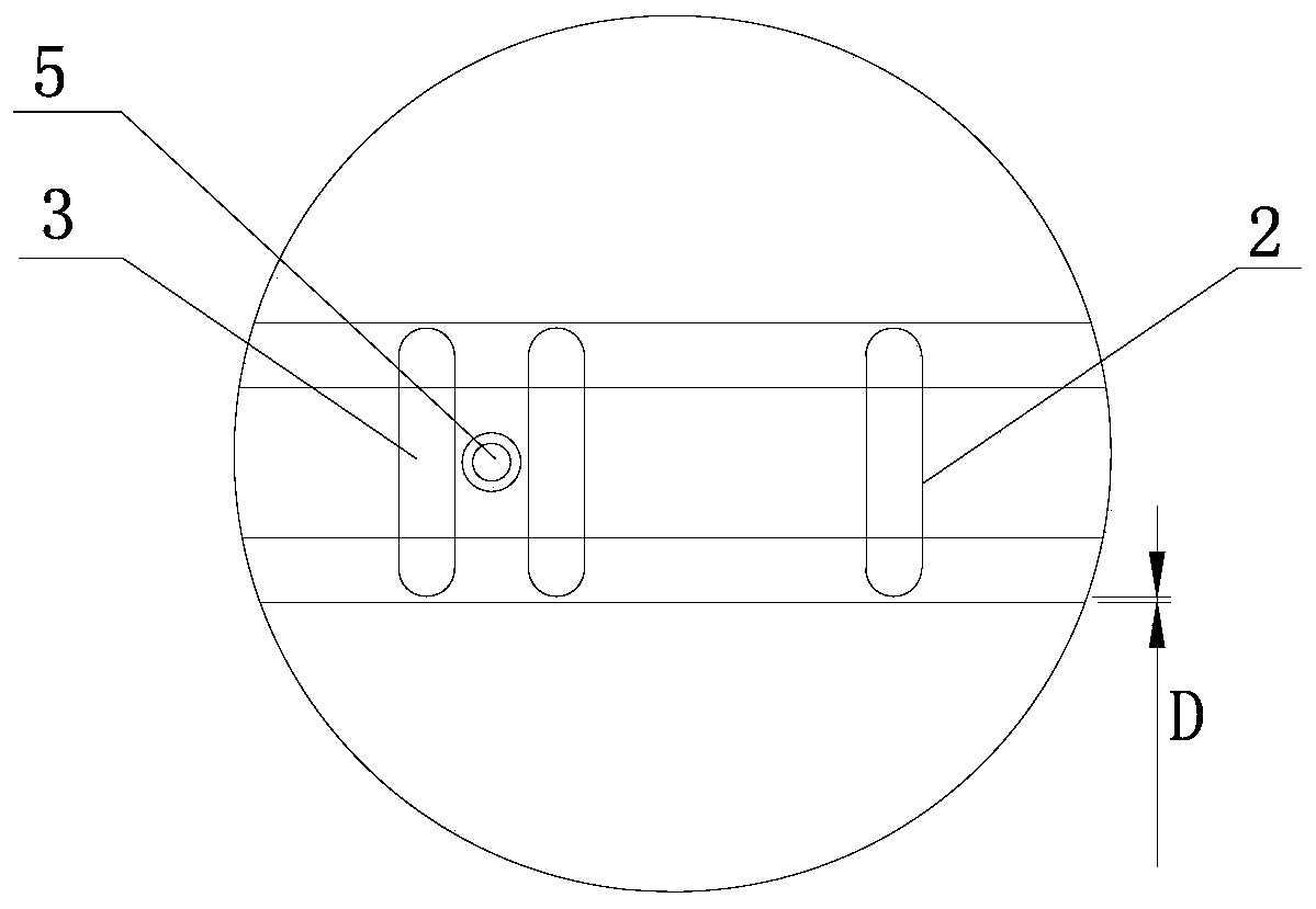
[0031] A magnetic pad suitable for a magnetic template proposed in this embodiment further defines the through hole 2 on the basis of the magnetic pad in Embodiment 1, that is, the thickness D of the hole wall of the through hole 2 is 1 ~2 mm. After opening a plurality of through holes 2 on the magnetizer 1, the magnetizer 1 is divided into a plurality of sub-magnetizers, and the adjacent two sub-magnetizers are connected by the walls of the through-holes 2, so that the plurality of sub-magnetizers are still As a whole, in order to ensure the connection strength between two adjacent sub-magnetic conductors, and to ensure that the area of ​​the non-magnetic conductor 3 is large enough to isolate the magnetic interference of the adjacent magnetic poles as much as possible, the hole wall of the through hole 2 is determined through a large number of experiments. The thickness is 1-2 mm, such as 1.5 mm.

Embodiment 3

[0033] A magnetic permeable pad suitable for a magnetic force template proposed in this embodiment, on the basis of the magnetic permeable pad in embodiment one or embodiment two, defines the width B of the wide lower part 41 of the magnetic permeable pad 4 and the narrow upper part 42 The width A of the width A, the height C of the narrow upper part 42, that is, the width B of the wide lower part 41 of the magnetic pad 4 is consistent with the width of the magnetic pole 81 on the magnetic template 8, so that under the isolation of the non-magnetic body 3, the magnetic template 8 is guaranteed. All the lines of force of each magnetic pole 81 on the top diverge completely vertically upwards, and there will be no magnetic leakage phenomenon; The width of 1.6 millimeters, when grinder 9 carries out the side end surface processing of guide rail 7 like this, emery wheel 91 can not touch the narrow upper part 42 of magnetic conduction pad 4 and damage magnetic conduction pad 4; The h...


PUM


Abstract

The invention discloses a magnetic conductive pad for a magnetic template. The magnetic conductive pad for the magnetic template comprises a magnetic conductive body matched with the magnetic templatein the longitudinal length direction, and the transverse section of the magnetic conductive body is shaped like a Chinese character 'tu'; the portions, corresponding to all resin layers of the magnetic template, of the magnetic conductive body are provided with through holes in the transverse direction, the through holes vertically penetrate through the magnetic conductive body, the two sides ofthe through holes are provided with hole walls, a non-magnetic conductive material is poured into the through holes, and a non-magnetic conductive body is formed after the non-magnetic conductive material is completely hardened; and the outer surface of the non-magnetic conductive body is flush with the outer surface of the magnetic conductive body, the non-magnetic conductive body and the magnetic conductive body are integrated to form the magnetic conductive pad, the narrow upper surface of the magnetic conductive pad serves as a workpiece installing surface, the wide low surface of the magnetic conductive pad serves as a magnetic template contact surface, and the magnetic conductive portions of the magnetic conductive pad correspond to magnetic poles of the magnetic template. The magnetic conductive pad for the magnetic template has the advantages that guide rail machining is convenient when the magnetic conductive pad is used, and the magnetic template can be well protected by themagnetic conductive pad.

Description

technical field [0001] The invention relates to a magnetically permeable pad, in particular to a magnetically permeable pad suitable for a magnetic template. Background technique [0002] With the rapid development of magnetic templates, it has been more and more applied to the field of grinding machines. However, due to the particularity of the grinding machine equipment, the installation of the magnetic template in the grinding machine basically covers the entire work surface of the grinding machine, and the workpiece is directly adsorbed on the surface of the magnetic template for processing during work. However, such a working method has the following problems: 1. ) Since the workpiece is in direct contact with the magnetic template, it is inevitable that it will bump into the magnetic template during multiple clamping projects, which will cause local high points on the surface of the magnetic template. It is necessary to give priority to grinding the high points in the ...

Claims


Application Information

Patent Timeline
Patent Type & Authority Applications(China)
IPC IPC(8): B24B55/00B24B41/06
CPCB24B41/06B24B55/00
Inventor 章建波陆秉贤陈旭彬张靖霍徐鼎刘辉刘斌吴朝华刘玉新陈健
Owner 宁波海迈克精密机械制造有限公司
Why Eureka
Try Eureka