Supercharge Your Innovation With Domain-Expert AI Agents!

Offset correction method, device and system for glass fixture

A glass fixture and offset correction technology, which is applied to printing devices, printing, typewriters, etc., can solve problems such as ink droplet deviation, fixture offset, and detection, so as to improve accuracy, ensure accuracy, and realize offset effect

Active Publication Date: 2019-08-06
GUANGDONG JUHUA PRINTING DISPLAY TECH CO LTD
View PDF12 Cites 1 Cited by
  • Summary
  • Abstract
  • Description
  • Claims
  • Application Information

AI Technical Summary

Problems solved by technology

However, the problem with the existing technology is that the fixture of the glass substrate may have an offset during the long-term movement, and these small offsets cannot be detected by the system for a period of time, so the following problems may occur:
[0004] 1. When the movement offset of the glass fixture in the Y direction is too large, it will directly lead to abnormal equipment and stop inkjet printing;
[0005] 2. When the movement offset of the glass fixture in the Y direction accumulates, although the equipment will not stop abnormally, it may cause ink droplets to deviate from the pixel pit at the end of the printing of the glass substrate, and then cause inkjet printing In the process, the ink material in the pixel pit on the glass substrate has uneven film thickness after decompression drying, which eventually leads to abnormal efficiency of inkjet printed OLED devices

Method used


Image

  • Offset correction method, device and system for glass fixture
  • Offset correction method, device and system for glass fixture
  • Offset correction method, device and system for glass fixture

Examples


Embodiment Construction

[0061] In order to make the object, technical solution and advantages of the present invention clearer, the present invention will be further described in detail below in conjunction with the accompanying drawings and embodiments. It should be understood that the specific embodiments described here are only used to explain the present invention, not to limit the present invention.

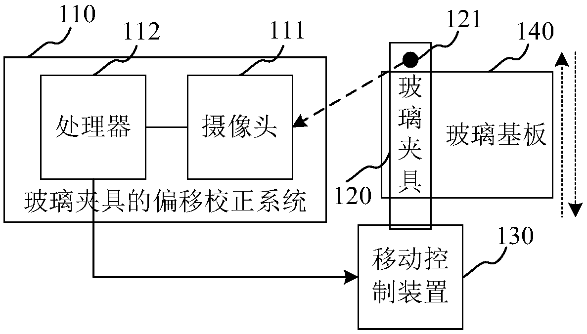
[0062] The offset correction method of the glass fixture provided by the present invention can be applied to such as figure 1 A glass fixture is shown in the deskew system 110 . Wherein, the offset correction system 110 of the glass fixture includes a camera 111 and a processor 112 connected to the camera 111, the processor 112 is connected to the movement control device 130 of the glass fixture 120, and the movement control device 130 is used to control the movement of the glass fixture 120. The fixture 120 moves, wherein the glass fixture 120 is provided with a logo 121, the processor 112 contro...


PUM


Abstract

The invention relates to an offset correction method for a glass fixture, an offset correction device for the glass fixture, an offset correction system for the glass fixture, computer equipment, anda computer readable storage medium. The method includes the following steps: detecting and obtaining a first position coordinate of a marking disposed on the glass fixture; controlling the glass fixture to move according to a set path, and detecting a second position coordinate of the obtained marking after the movement of the glass fixture according to the set path; according to the first position coordinate and the second position coordinate, obtaining offset of a position of the marking before and after the movement of the glass fixture according to the set path; and performing compensationcorrection on the position of the glass fixture according to the offset of the position of the marking. According to the method, through recognition of the marking disposed on the glass fixture, theoffset of the position of the marking before and after the movement is obtained, the compensation correction is performed on the position of the glass fixture according to the offset of the position,and so, the offset of the glass fixture during an inkjet printing process is avoided, and the positional accuracy of an ink droplet dropping on a glass substrate is improved.

Description

technical field [0001] The present invention relates to the technical field of inkjet printing, in particular to a glass fixture offset correction method, a glass fixture offset correction device, a glass fixture offset correction system, computer equipment and a computer-readable storage medium. Background technique [0002] Inkjet printing technology has been widely used in the device manufacturing process in addition to the printing of traditional paper text patterns. For example, some functional materials in the OLED device manufacturing process can use inkjet printing technology, such as the hole injection layer ( HIL), hole transport layer (HTL), light emitting layer material (EML), etc. That is, in the known pixel pits, the functional layer material ink is injected into the pixel pits by means of inkjet printing. According to the characteristics of the inkjet printing process, the uniformity of the film thickness of the ink material filled in the pixel pit is an impo...

Claims


Application Information

Patent Timeline
IPC IPC(8): B41J2/01B41J3/407B41J11/00
CPCB41J2/01B41J3/407B41J11/00
Inventor 柳开郎
Owner GUANGDONG JUHUA PRINTING DISPLAY TECH CO LTD
Features
  • R&D
  • Intellectual Property
  • Life Sciences
  • Materials
  • Tech Scout
  • Unparalleled Data Quality
  • Higher Quality Content
  • 60% Fewer Hallucinations
Learn More