High-speed train braking force optimal distribution method

A technology for optimizing allocation and high-speed trains, applied in brakes, railway braking systems, braking transmissions, etc., can solve problems such as less consideration of adhesion limit differences, train slippage, etc.

Active Publication Date: 2019-08-06
HUNAN UNIV OF TECH
View PDF6 Cites 8 Cited by
  • Summary
  • Abstract
  • Description
  • Claims
  • Application Information

AI Technical Summary

Problems solved by technology

[0005] The purpose of the present invention is to construct a method for optimal distribution of braking force of high-speed trains, which is used to solve the problem that the exi

Method used


Image

  • High-speed train braking force optimal distribution method
  • High-speed train braking force optimal distribution method
  • High-speed train braking force optimal distribution method

Examples


Embodiment 1

[0056] 1 Optimal distribution strategy of air braking force based on maximum adhesion utilization

[0057] 1.1 Objective function

[0058] The coefficient of adhesion μ that would normally be utilized in the locomotive adhesion concept L The ratio to the available stickiness coefficient μ is defined as sticky utilization:

[0059]

[0060] The available sticking coefficients and the used sticking coefficients are expressed as follows:

[0061]

[0062]

[0063] From formula (1) (2) (3), the equivalent expression of adhesion utilization rate can be obtained

[0064]

[0065] In the formula: F is the adhesion force (KN) utilized, F max is the maximum adhesion force (KN) that can be produced between the wheel and rail, and p is the vertical static load (KN).

[0066] According to the requirements of braking force distribution, it is necessary to maximize η, which is equivalent to (1-η) 2 minimum. The air braking force distribution of 4 vehicles is taken as an ex...

Embodiment 2

[0121] 1 Simulation and experiment

[0122] 1.1 Simulation results and analysis

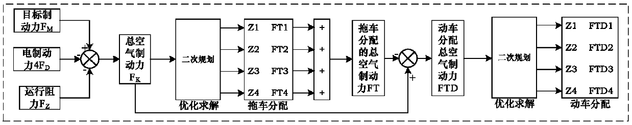
[0123] Aiming at the distribution of braking force during the train braking process, the simulation model of fast braking conditions is established by using MATLAB / SIMULINK as follows: figure 1 authenticating.

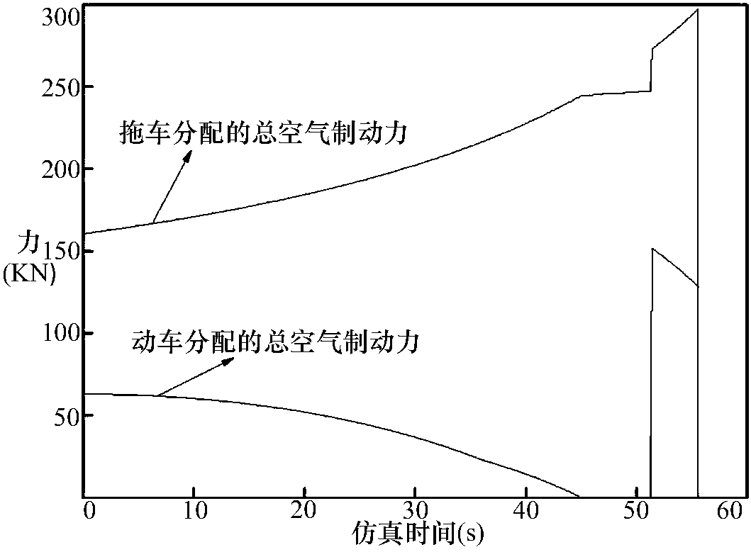
[0124] Such as image 3 Shown is the total air braking force distributed by the motor car and the trailer during the braking process. It can be seen that the total air braking force distributed by the trailer has been increasing, and the motor car has been decreasing accordingly until it is zero. After 50s, since the electric braking force is zero, the trailer can no longer meet the braking requirements, and the air braking force of the train needs to be supplemented.

[0125] Such as Figure 4-7 Shown is the comparison of air braking force distribution and load-to-weight ratio distribution of 4 trailers using the optimal distribution algorithm of the present invention, by Figure 4-...


PUM


Abstract

The invention discloses a high-speed train braking force optimal distribution method which can be used for an electric-air braking force distribution strategy of a high-speed train; the method has thefollowing steps: firstly, building a mathematical model of a high-speed train braking process, and calculation of an object braking force, an electric braking force and an operation resistance is included; secondly, designing an objective function and constraint conditions for brake force optimal distribution, and proving the existence of an extreme value of the objective function; and then converting the established objective function and constraint conditions into a quadratic plan for solving. And finally, simulation shows that the distribution method not only can fully utilize different adhesion limits of each vehicle to effectively exert the available braking force of each vehicle, but also can reduce the slipping phenomenon of the bullet trains in a wet rail surface braking process,and is beneficial to improving the braking performance of the train and improving the braking efficiency.

Description

technical field [0001] The invention belongs to the technical field of high-speed train control, and in particular relates to a method for optimal distribution of braking force of a high-speed train. Background technique [0002] High-speed trains have become the direction and goal of my country's railway development in the future. With the continuous speed up of trains, the safety performance indicators of railway transportation are also increasing day by day. Safety is the most important criterion for measuring the quality of transportation, so the braking system must have high reliability. [0003] When the train brakes, the braking force exerted on each car depends on the adhesion formed between the wheel set and the rail during the contact process. Due to the limitation of the adhesion coefficient between the wheel and the rail, the braking force applied by the vehicle cannot be too large. If the adhesion limit between the wheel and rail is exceeded, sliding will occ...

Claims


Application Information

Patent Timeline
IPC IPC(8): B60T8/1761B60T13/74B61H11/14
CPCB60T8/1761B60T13/74B61H11/14
Inventor 何静史来诚张昌凡杨步充何云国
Owner HUNAN UNIV OF TECH
Why Eureka
Try Eureka