LT type elastic sleeve pin coupling

A technology of pin coupling and elastic sleeve, applied in the direction of elastic coupling, coupling, mechanical equipment, etc., can solve the problems of easy collision, scrapped parts, not easy to disassemble, etc., so as to prolong the service life and improve the Service life, easy assembly and positioning effect

Inactive Publication Date: 2019-08-06
JIANGSU ROKEE HEAVY IND TECH
View PDF5 Cites 4 Cited by
  • Summary
  • Abstract
  • Description
  • Claims
  • Application Information

AI Technical Summary

Problems solved by technology

[0003] Due to the high impact force of the coupling during high-speed rotation, especially the main shaft on the motor is connected to the reducer through the coupling, after installation and adjustment, a certain impact load will be generated during high-speed operation. The parts on the shaft are damaged, and the two half-couplings of the coupling are in rigid contact. After a period of time, the coupling shaft and the hole also start to wear, which is prone to collision damage, which eventually leads to the complete failure of the entire set of parts. scrapped, seriously affecting the service life of the coupling; moreover, most of the existing TL-type elastic sleeve pin couplings only place elastic parts in one half of the coupling to increase its elasticity, but when the coupling When the impact force is high during high-speed rotation, this configuration is often difficult to meet its shockproof needs; moreover, the general TL-type elastic sleeve pin coupling, the two half-coupling contact surfaces are in planar contact, and attention should be paid when assembling The positioning of the shaft hole is inconvenient to operate and there is a problem of misinstallation
In addition, due to the complex structure of the coupling, it is not easy to disassemble. If the machine has not been used for a long time, the shaft hole inside the coupling is prone to rust spots, which will affect the efficiency of the machine; these problems need to be improved urgently

Method used


Image

  • LT type elastic sleeve pin coupling
  • LT type elastic sleeve pin coupling
  • LT type elastic sleeve pin coupling

Examples


Embodiment Construction

[0024] The technical solution of the present invention will be clearly and completely described below in conjunction with specific embodiments:

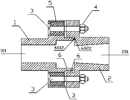
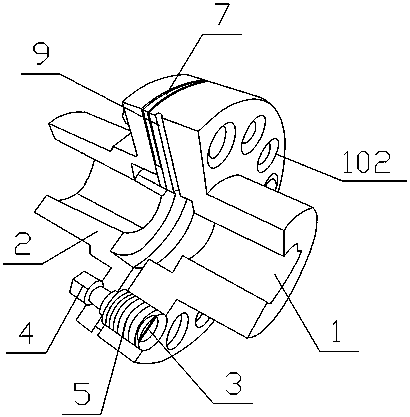
[0025] A LT-type elastic sleeve pin coupling, refer to Figure 1 to Figure 8 , including left half coupling 1, right half coupling 2, several fastening pins 3, several fastening nuts 4 and several elastic sleeves 5; said left half coupling 1 and right half coupling The connectors 2 are all T-shaped. Several elastic sleeve placement holes 103 are evenly arranged around the left shaft hole 102 on the connecting surface 101 of the left half coupling, and the connecting surface 201 of the right half coupling surrounds the left shaft hole 202 and Bolt holes 203 are set at the positions corresponding to the elastic sleeve placement holes 103 of the left half coupling; 5 through and through the bolt hole 201 of the right half coupling 2 is connected with the fastening nut 4, and the contacting side of the left half coupling 1 and the right...


PUM


Abstract

The invention discloses an LT type elastic sleeve pin coupling. The coupling includes a left half-coupling, a right half-coupling, multiple fastening pins, multiple fastening nuts and multiple elasticsleeves. A surface where the left half-coupling and the right half-coupling are in contact is provided with a matching positioning device, which facilitates assembly and positioning and effectively solves the problem of wrong mounting. An integral shock absorbing pad is arranged between the left half-coupling and the right half-coupling, A shockproof sleeve and a shockproof washer are arranged onthe positioning device surface, which strengthens the shockproof performance of the coupling. In addition, the connecting surface side of the left half-coupling of the coupling is also provided withan oil filling hole communicating with a shaft hole so as to oil for rust prevention. The LT type elastic sleeve pin coupling has the advantages of simple structure, reasonable arrangement and low manufacturing cost, effectively reduces the wear and rust prevention problem between a coupling shaft and the hole, and has good use value.

Description

technical field [0001] The invention relates to a shaft coupling, in particular to an LT type elastic sleeve pin coupling, which belongs to the field of mechanical manufacturing. Background technique [0002] Coupling refers to the connection of two shafts or shafts and rotating parts, which rotate together during the transmission of motion and power, and sometimes play the role of overload protection. The coupling can also compensate for the offset between the two shafts due to inaccurate manufacturing and installation, deformation or thermal expansion during work, as well as the functions of mitigating impact and absorbing vibration. Couplings can be divided into two categories: rigid couplings and flexible couplings. Flexible couplings can be divided into flexible couplings without elastic elements and flexible couplings with elastic elements. TL type elastic The sleeve pin coupling is an ordinary elastic coupling with a wide range of applications, belonging to the scope...

Claims


Application Information

Patent Timeline
Patent Type & Authority Applications(China)
IPC IPC(8): F16D3/70
CPCF16D3/70
Inventor 石光洲
Owner JIANGSU ROKEE HEAVY IND TECH
Why Eureka
Try Eureka