Current type bidirectional bending sensor and preparation method thereof
A current type, sensor technology, applied in the field of sensors, can solve the problem of inability to measure the degree of bending in both directions, and achieve the effect of wide application, high measurement accuracy, and good measurement effect.
- Summary
- Abstract
- Description
- Claims
- Application Information
AI Technical Summary
Problems solved by technology
Method used
Image

Examples
Embodiment 1
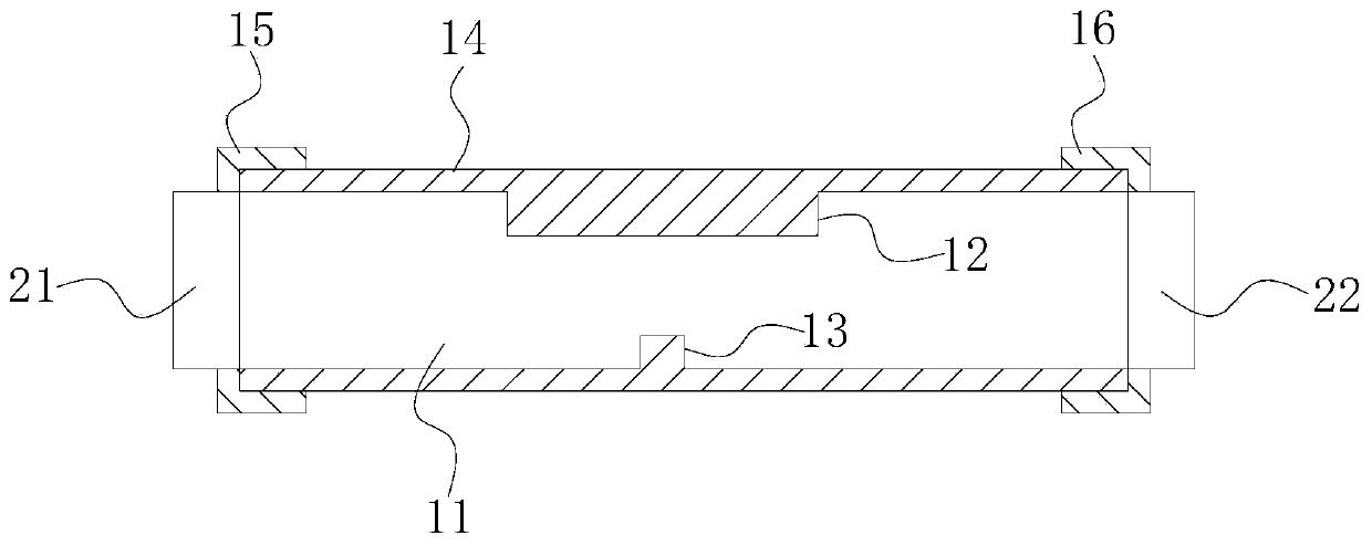
[0049] Amperometric bidirectional bending sensors such as Figure 1 to Figure 7 As shown, it includes a light emitting component 21, a light receiving component 22 and a flexible light guide element, the refractive index of the light guide element is greater than 1, and the light guide element is an optical fiber in this embodiment. The change of the luminous flux of the light guide element in the bidirectional bending process is monotonous, and the light emitting assembly 21 and the light receiving assembly 22 are respectively fixedly installed on the two ends of the light guide element, the light emitting assembly 21 includes a light emitting element, and the light receiving assembly 22 includes a light emitting element. A receiving element, a light emitting element and a light receiving element are located at both ends of the light guide element, respectively.
[0050] The light-emitting element is an active light-emitting device in which the amount of light emitted is prop...
Embodiment 2
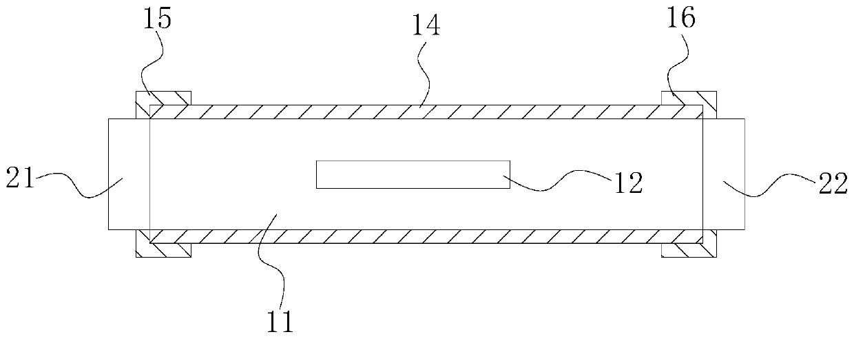
[0088] A new type of light guiding element, such as Figure 8 As shown, the difference between it and Embodiment 1 is that in the unit length section: there are multiple light dissipation grooves 12, and the sum of the inner surface areas of the plurality of light dissipation grooves 12 is not less than 4% of the inner surface area of the whispering wall blocking groove 13. times.
[0089] In a unit length section: a plurality of light dissipation grooves 12 are arranged along the extending direction of the light guide body 11 .
[0090] This embodiment has the following advantages:
[0091] By setting a plurality of light dissipation grooves 12 in different positions, the light guide body 11 can change the luminous flux and eliminate the bending loss oscillation phenomenon through the light dissipation grooves 12 when the light guide body 11 is bent at different positions, so as to improve applicability and facilitate use Effect.
Embodiment 3
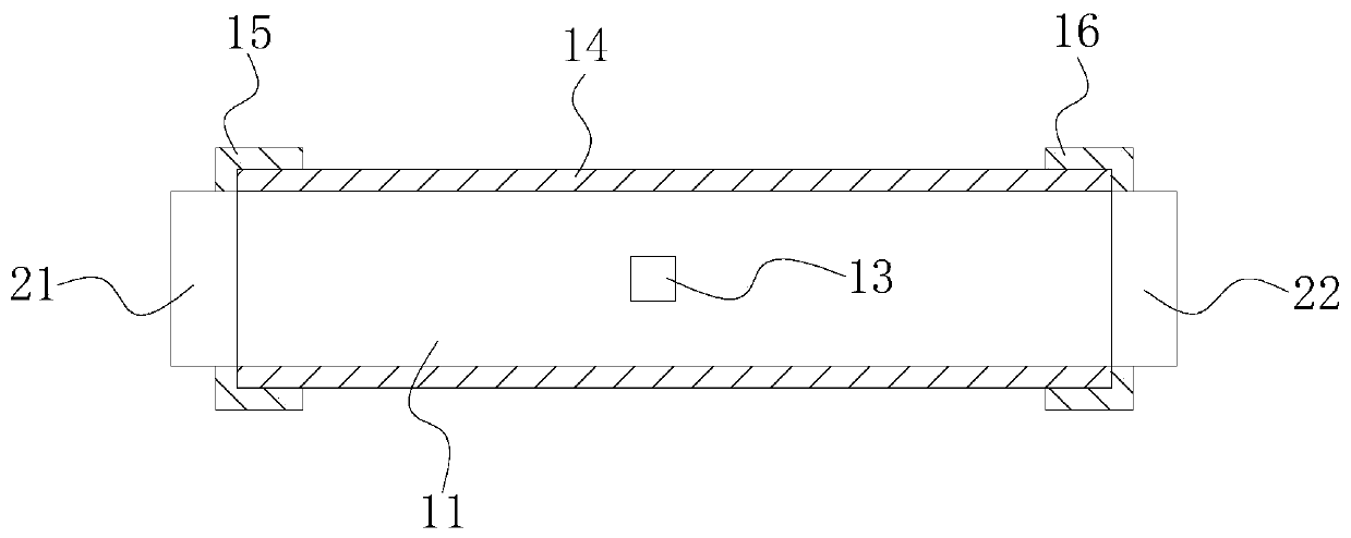
[0093] A new type of light guiding element, such as Figure 9 and Figure 10 As shown, the difference between it and Embodiment 2 is that within a unit length section: three light dissipation grooves 12 are provided, and the three light dissipation grooves 12 are arranged along the circumferential direction of the light guide body 11 .
[0094] In the unit length section: there are three whispering wall blocking grooves 13, the sum of the inner surface areas of the three light escape grooves 12 is not less than four times the sum of the inner surface areas of multiple whispering wall blocking grooves 13, and the three light escape grooves The loose grooves are arranged along the circumferential direction of the light guide body 11 .
[0095] This embodiment has the following advantages:
[0096] By setting a plurality of light dissipation grooves 12 and whispering wall blocking grooves 13 in different positions, the light guide body 11 can change the luminous flux and elimin...
PUM
 Abstract
Description
Claims
Application Information
 - R&D
- Intellectual Property
- Life Sciences
- Materials
- Tech Scout
- Unparalleled Data Quality
- Higher Quality Content
- 60% Fewer Hallucinations
Browse by: Latest US Patents, China's latest patents, Technical Efficacy Thesaurus, Application Domain, Technology Topic, Popular Technical Reports.
© 2025 PatSnap. All rights reserved.Legal|Privacy policy|Modern Slavery Act Transparency Statement|Sitemap|About US| Contact US: help@patsnap.com