Thermal resistance correction method considering influence of thermocouple glue for IGBT aging experiment

An aging experiment, thermocouple technology, applied in the direction of measuring electricity, measuring electrical variables, measuring devices, etc., can solve problems such as thermal resistance correction without explanation, and achieve the effect of simple and intuitive correction method, easy operation, and improved accuracy.

Active Publication Date: 2019-08-06
HEFEI UNIV OF TECH
View PDF5 Cites 2 Cited by
  • Summary
  • Abstract
  • Description
  • Claims
  • Application Information

AI Technical Summary

Problems solved by technology

[0005] The above-mentioned inventions all explain that the thermocouple needs to be used to obtain the shell temperature in the process of thermal resistance extraction, but none of them explain the problem of thermal resistance correction considering the influence of thermocouple glue. to solve the problem of measurement error, a correction method for thermal resistance is proposed

Method used


Image

  • Thermal resistance correction method considering influence of thermocouple glue for IGBT aging experiment
  • Thermal resistance correction method considering influence of thermocouple glue for IGBT aging experiment
  • Thermal resistance correction method considering influence of thermocouple glue for IGBT aging experiment

Examples


Embodiment 1

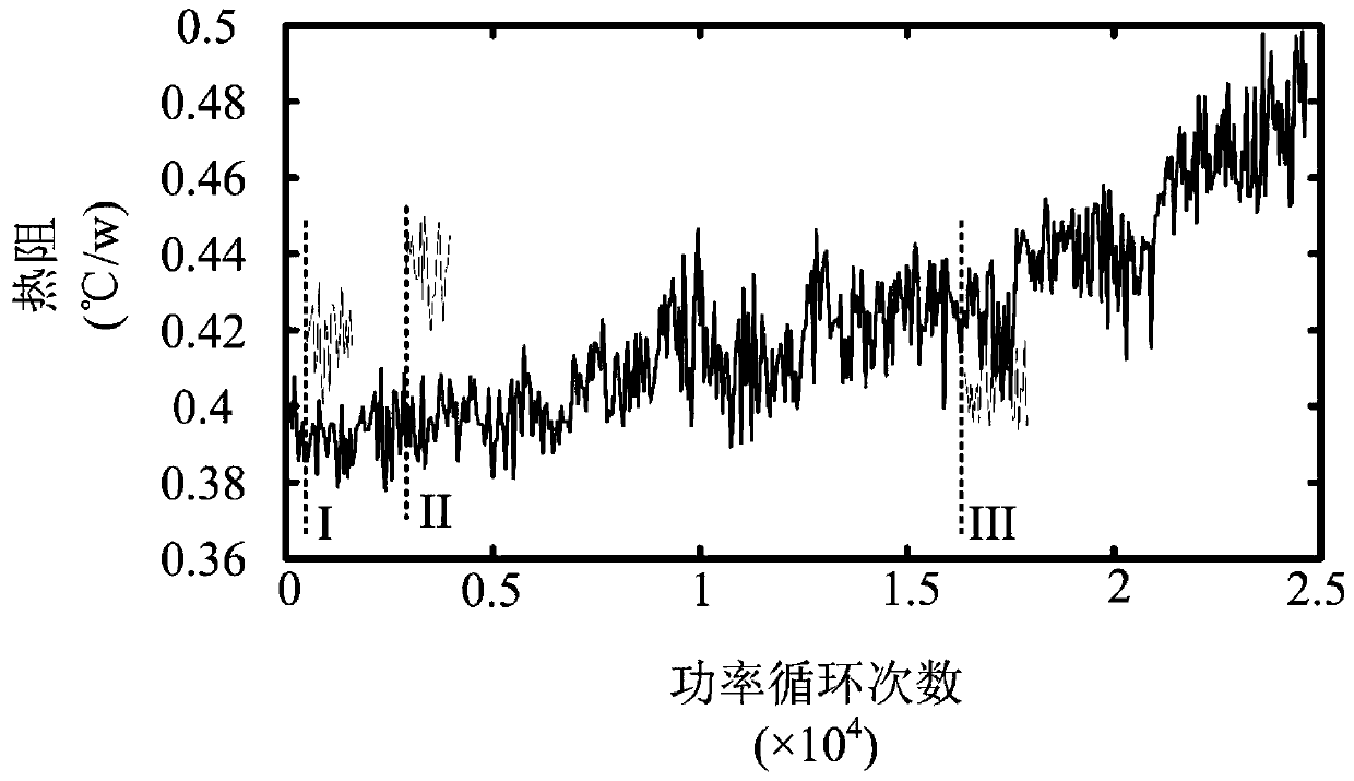
[0102] Example 1: The glue loosened during the 2853rd power cycle, so that the thermal resistance value R th(2853) Equal to the thermal resistance value R obtained in the 2852th power cycle th(2852) , and obtain the shell temperature correction ΔT needed for the subsequent power cycle c2853 , then the thermal resistance value R extracted by this power cycle th(2853) and the shell temperature correction ΔT required for subsequent power cycles c2853 They are:

[0103] R th(2853) =R th(2852) =0.4086

[0104] ΔT c2853 =(T j "-T j0 ”)-(T c2 "-T c0 ”)-R th(2852) P" = 2.607°C.

Embodiment 2

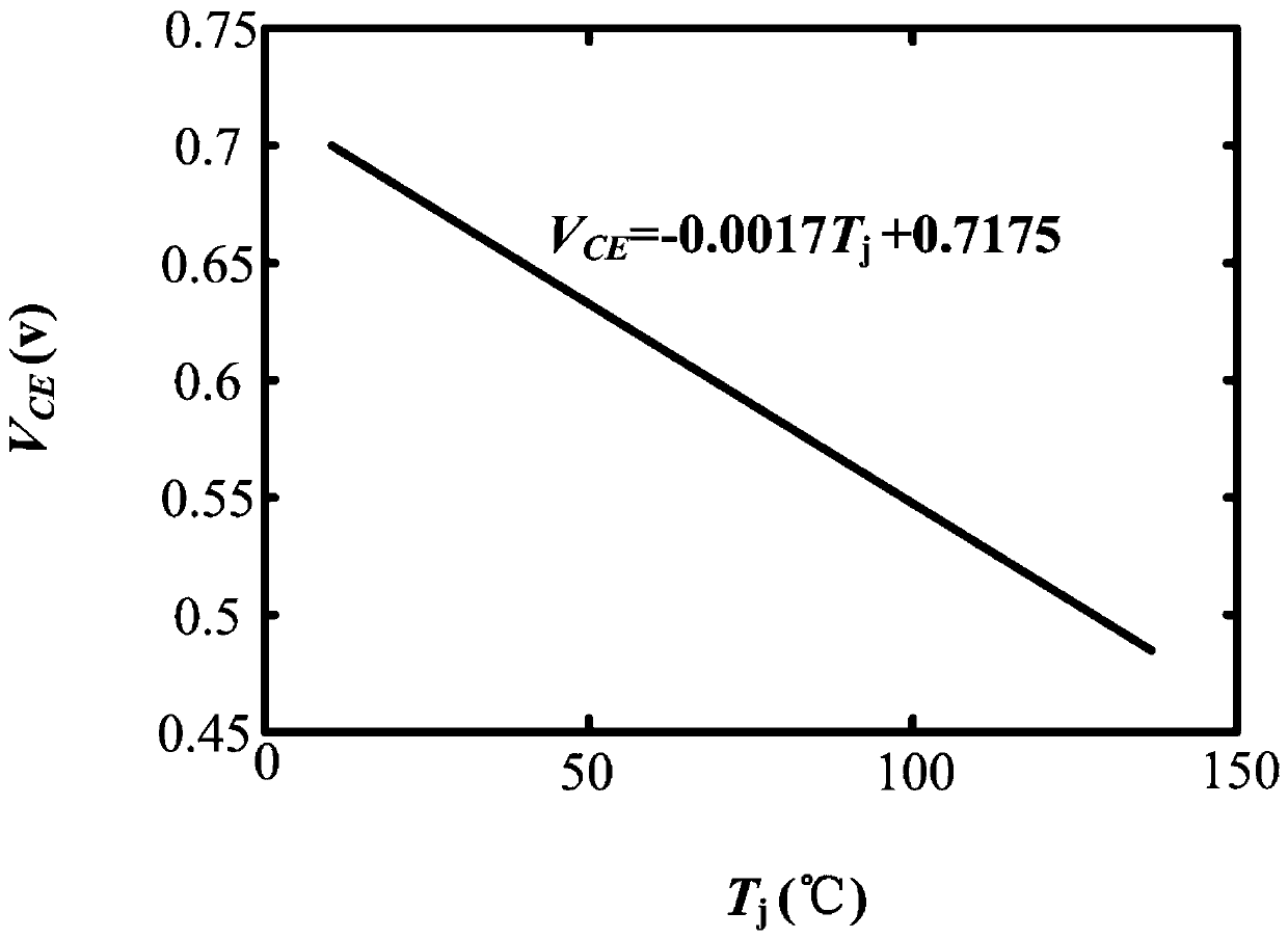
[0105] Example 2: n=5750. If the glue does not loosen during the 5750th power cycle, then proceed to the next step of judgment. In this embodiment 2, n=5750, k=2853, V CE0 "=0.6247V, the corresponding T j0 ”=54.56°C. T measured by thermocouple c0 ” = 42.87°C, V CE "=0.5061V, the corresponding T j ”=124.38°C. T measured by thermocouple c2 ” = 68.44°C, V CEL "=1.6982V, the corresponding P"=101.89W, ΔT c2853 = 2.607°C. That is, in the 2853th power cycle between the 1st power cycle and the 5750th power cycle, the glue loosened and the thickness of the glue after replacement increased, then the thermal resistance value extracted by the 5750th power cycle was:

[0106]

[0107] where ΔT c2853 Case temperature correction for the 2853rd power cycle.

Embodiment 3

[0108] Embodiment 3: n=19421, k=16359, V CE0 "=0.6162V, the corresponding T j0 ”=59.61℃. T is obtained by thermocouple measurement c0 " = 46.99°C; V CE "=0.4953V, the corresponding T j ”=130.69℃. Through the IGBT module case temperature T c2 ” = 72.68°C, V CEL "=1.7243V, the corresponding P"=103.46W, ΔT c16359 = 1.036°C. That is, in the 16359th power cycle between the 1st power cycle and the 19421st power cycle, the glue loosened and the thickness of the glue after replacement decreased, then the thermal resistance value R extracted from the 19421st power cycle th(19421) for:

[0109]

[0110] where ΔT c16359 Case temperature correction for the 16359th power cycle.


PUM


Abstract

The invention discloses a thermal resistance correction method considering influence of thermocouple glue for an IGBT aging experiment. The method is based on a power cycling accelerated aging experiment of an IGBT module, and takes influence of fall-off and replacement of the thermocouple glue in the experimental process on a thermal resistance extracted value. In the thermal resistance extraction process in the experiment, thermal resistance correction calculation formulas corresponding to different conditions are selected by determination for multiple times, and the extracted value is corrected. The experimental result is more accurate, and it is ensured that the aging degree of the IGBT module is not misjudged due to influence of the thermocouple glue in the accelerated aging experiment process. The correction method is simple, visual and easy to operate.

Description

technical field [0001] The invention relates to a method for calculating the thermal resistance of an IGBT aging experiment, in particular to a method for correcting the thermal resistance of an IGBT aging experiment considering the influence of thermocouple glue. Background technique [0002] Insulated gate bipolar transistor (IGBT) power module is one of the most commonly used switching devices in power electronic systems, so its reliability has attracted much attention. At present, accelerated aging experiments have been widely used to study the evolution process and failure mechanism of IGBT modules under large loads. Accelerated aging experiments include power cycling and temperature cycling. Compared with temperature cycling, power cycling is more in line with the actual aging of IGBT modules. Therefore, power cycle experiments are widely used to study the failure process of IGBT modules. During the aging process, the main failure types of the IGBT module are bonding...

Claims


Application Information

Patent Timeline
Patent Type & Authority Applications(China)
IPC IPC(8): G01R31/00
CPCG01R31/003
Inventor 马铭遥詹铭玥郭伟生张久柱王佳宁张兴
Owner HEFEI UNIV OF TECH
Why Eureka
Try Eureka