Capacitive coupling device and filter containing capacitive coupling device

A capacitive coupling and negative coupling technology, applied in the direction of connecting devices, waveguide devices, electrical components, etc., can solve the problems of consuming man-hours, increasing the production process of dielectric filters, etc., to achieve convenient processing, convenient processing and manufacturing, and improve performance Effect

Pending Publication Date: 2019-08-06
WUHAN FINGU ELECTRONICS TECH
View PDF0 Cites 16 Cited by
  • Summary
  • Abstract
  • Description
  • Claims
  • Application Information

AI Technical Summary

Problems solved by technology

This technical solution realizes capacitive coupling between the resonators on both sides of the blind hole by punching a blind hole on the dielectric body. However, the depth requirement of the blind hole will increase the manufacturing process of the dielectric filter. When the device is mass-produced will undoubtedly consume many man-hours

Method used


Image

  • Capacitive coupling device and filter containing capacitive coupling device
  • Capacitive coupling device and filter containing capacitive coupling device
  • Capacitive coupling device and filter containing capacitive coupling device

Examples


Embodiment 1

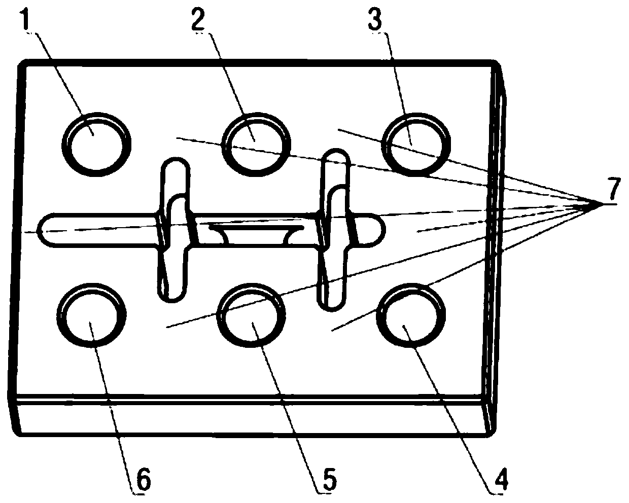
[0044] Attached by the description of the present invention Figure 1-4 It can be seen that the present invention discloses a capacitive coupling device, which includes a dielectric body, and six resonant frequency tuning holes are processed on the top surface of the dielectric body, namely the first resonant frequency tuning hole 1 and the second resonant frequency tuning hole 2 , the third resonant frequency tuning hole 3, the fourth resonant frequency tuning hole 4, the fifth resonant frequency tuning hole 5 and the sixth resonant frequency tuning hole 6, the six resonant frequency tuning holes are integrally formed, the first resonant frequency tuning hole 1 between the second resonance frequency tuning hole 2, between the second resonance frequency tuning hole 2 and the third resonance frequency tuning hole 3, between the third resonance frequency tuning hole 3 and the fourth resonance frequency tuning hole 4, and the fourth resonance Between the frequency tuning hole 4 a...

Embodiment 2

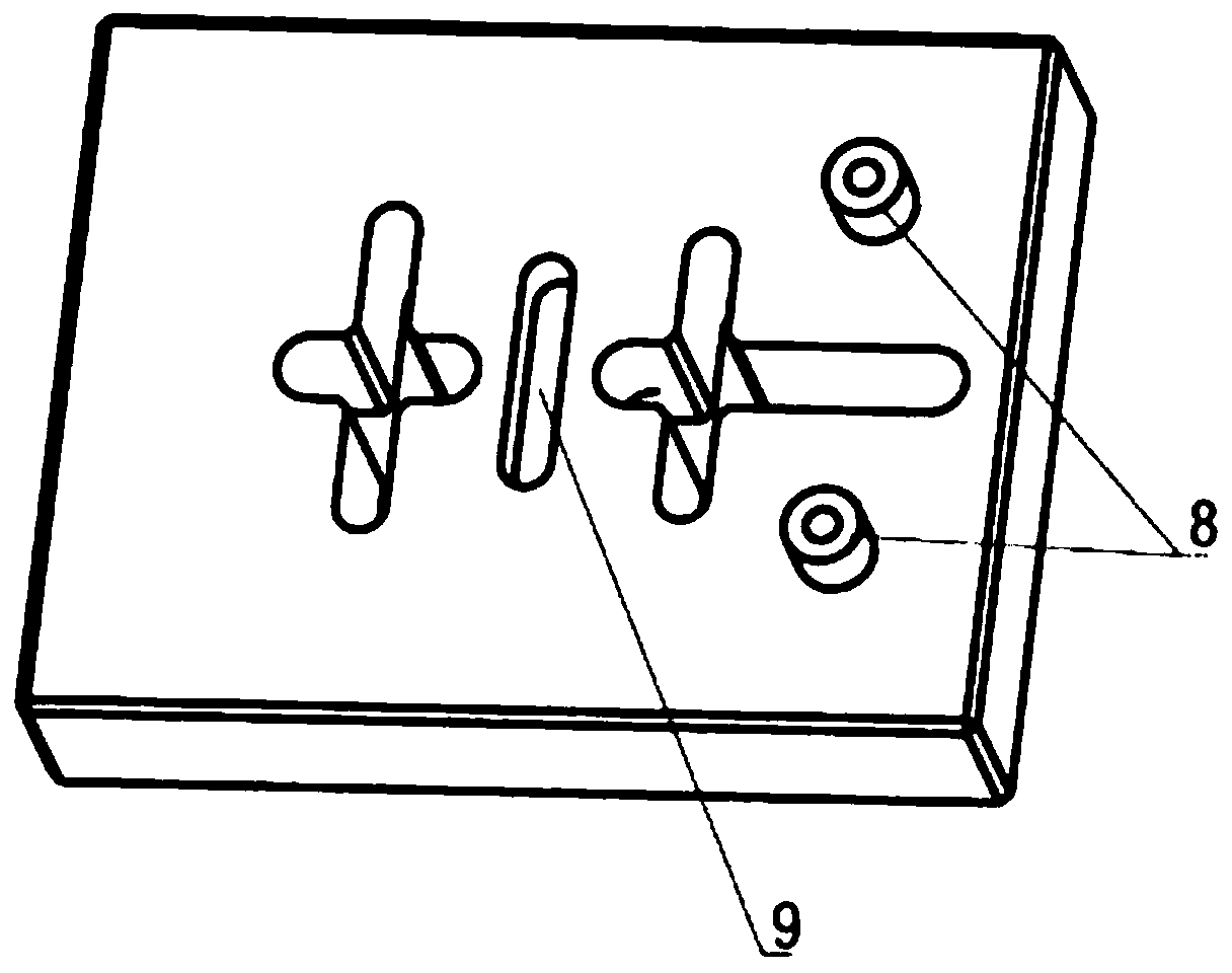
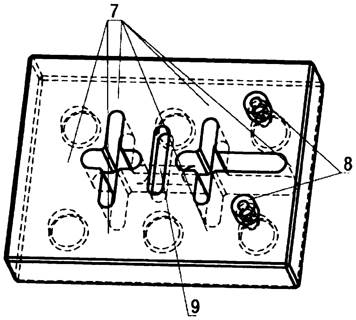
[0048] Attached by the description of the present invention Figure 6-8 It can be seen that the present invention discloses a capacitive coupling device, which includes a dielectric body, six resonant frequency tuning holes are processed on the top surface of the dielectric body, and an inductive coupling structure 7 is arranged between two adjacent resonant frequency tuning holes. The coupling structure 7 is a cross-shaped through hole, and a negative coupling groove 9 is also processed on the top surface of the dielectric body. The negative coupling groove 9 is a circular through hole, and the negative coupling groove 9 is located in the middle of the two adjacent resonance frequency tuning holes. Between, the outer surface of the dielectric body and the inner surfaces of the six resonant frequency tuning holes are plated with the first conductive metal layer, the inner surface of the negative coupling groove 9 is plated with the second metal conductive layer, and the two neg...

Embodiment 3

[0050] Attached by the description of the present invention Figure 9 It can be seen that the present invention discloses a capacitive coupling device, which includes a dielectric body, six resonant frequency tuning holes are processed on the top surface of the dielectric body, and an inductive coupling structure 7 is arranged between two adjacent resonant frequency tuning holes. The coupling structure 7 is a cross-shaped through hole, and a negative coupling groove 9 is also processed on the top surface of the dielectric body. The negative coupling groove 9 is a circular blind hole, and the negative coupling groove 9 is located in the middle of the two adjacent resonance frequency tuning holes. Between, the outer surface of the dielectric body and the inner surface of the 6 resonant frequency tuning holes are plated with the first metal conductive layer, the inner surface of the negative coupling groove 9 is plated with the second metal conductive layer, the notch of the negat...


PUM


Abstract

The invention discloses a capacitive coupling device and a filter containing the capacitive coupling device. The capacitive coupling device comprises a dielectric body. Multiple resonance frequency tuning holes are arranged in the surface of the dielectric body. A first conductive layer is plated on the surface of the dielectric body and the resonance frequency tuning holes. A negative coupling slot is arranged in the surface of the dielectric body between two adjacent resonance frequency tuning holes. A second conductive layer is arranged in the negative coupling slot. The capacitive couplingdevice is characterized in that an insulating layer for insulating the first conductive layer and the second conductive layer is arranged on the surface of the dielectric body around the negative coupling slot. Capacitive coupling between dielectric filters is realized, the performance of filters is improved, and the size of filters is reduced. Moreover, there is no need to further limit the processing depth and width of the negative coupling slot, and the processing and manufacturing of the capacitive coupling device are facilitated.

Description

technical field [0001] The invention relates to a capacitive coupling device, which belongs to the technical field of communication, in particular to a capacitive coupling device and a filter containing the capacitive coupling device. Background technique [0002] In the field of mobile communication, with the development of technology, the performance requirements of filters in the system are getting higher and higher. With the improvement of requirements, the high-power microwave filter at the base station has the characteristics of high index, small size and low cost. When realizing these high-performance filters, limited by the size of the cavity, the filters need to be realized using new materials or technologies. [0003] Limited by the material characteristics of the dielectric filter, it is generally necessary to add a transmission zero point when designing the filter. Dielectric filters are more difficult to achieve capacitive cross-coupling than metal filters. A...

Claims


Application Information

Patent Timeline
Patent Type & Authority Applications(China)
IPC IPC(8): H01P5/02H01P1/20
CPCH01P1/20H01P1/2002H01P5/02
Inventor 刘文朱晖金锐
Owner WUHAN FINGU ELECTRONICS TECH
Why Eureka
Try Eureka