A new energy vehicle charging anti-falling mechanism
A new energy vehicle, vehicle charging technology, applied in electric vehicle charging technology, charging station, electric vehicle and other directions, can solve the problems of low safety, low operation difficulty, inconvenient operation of the locking mechanism, etc., to improve safety, increase Contact area, good power transmission effect
- Summary
- Abstract
- Description
- Claims
- Application Information
AI Technical Summary
Problems solved by technology
Method used
Image
Examples
Embodiment 1
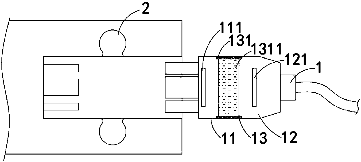
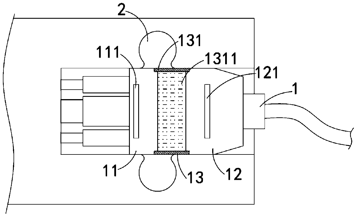
[0031] Such as Figure 1-3 As shown, a new energy vehicle charging anti-falling mechanism includes a charging head 1 and a limit groove 2 arranged in the charging port of the car. The charging head 1 includes:
[0032] The conductive head 11, the front end of the conductive head 11 is provided with a plug, the charging port of the car is provided with a corresponding plug rod, the rear end of the conductive head 11 is the first conductive surface, and the conductive head 11 is embedded with a first permanent magnet. sheet 111;
[0033] Hold the head 12, the rear end of the hold head 12 is electrically connected to the external power line, the front end of the hold head 12 is the second conductive surface, and the first conductive surface and the second conductive surface are passed between the conductive head 11 and the hold head 12. The contact between the conductive surfaces realizes power transmission, and the holding head 12 is embedded with a second permanent magnet piec...
Embodiment 2
[0040] Such as Figure 4 As shown, the difference between this embodiment and embodiment 1 is that: the first conductive surface is a convex arc surface, the second conductive surface is a concave arc surface, and the first conductive surface and the second conductive surface match.
[0041] In this embodiment, in the process of moving the second conductive surface to the first conductive surface, it is easier to squeeze the insulating liquid into the elastic connecting cylinder 131. At the same time, since the first conductive surface and the second conductive surface are arc-shaped, The contact area is increased to improve the stability of power transmission.
Embodiment 3
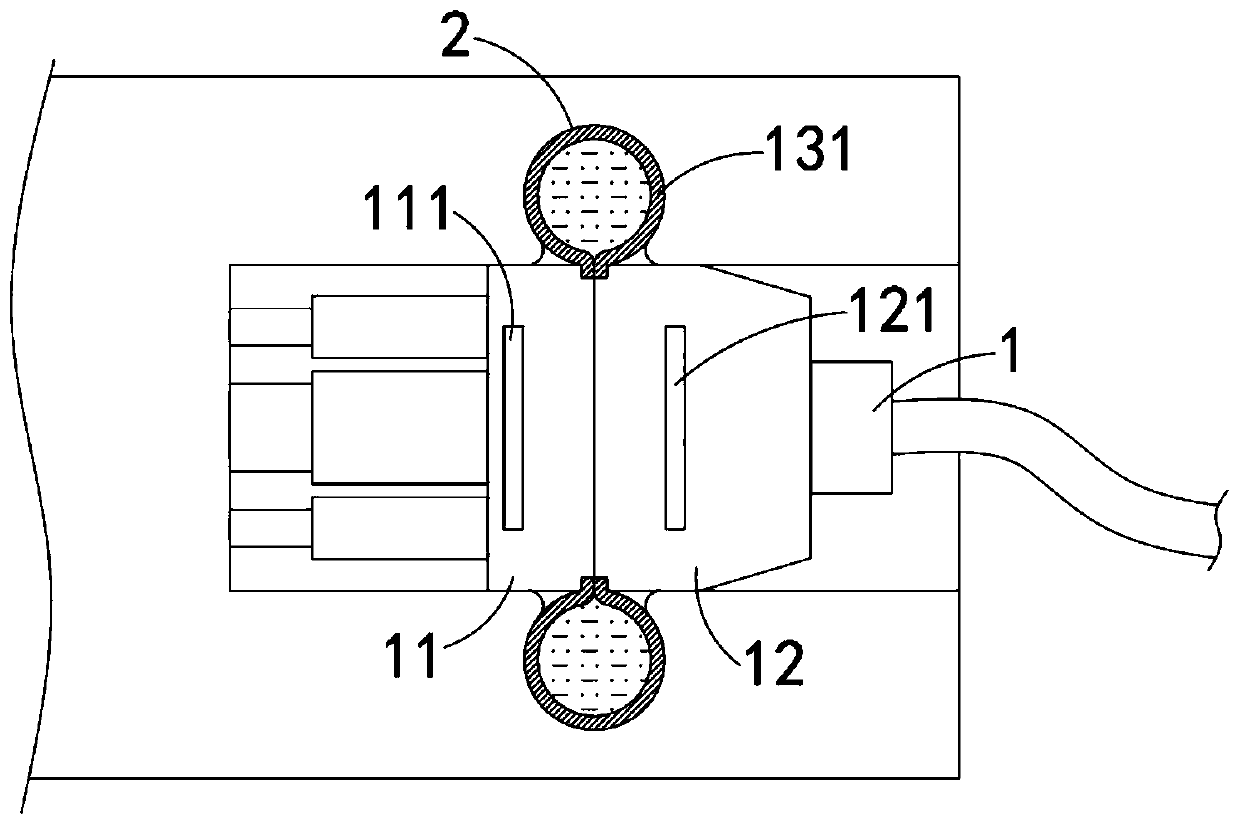
[0043] Such as Figure 5-7 As shown, the difference between this embodiment and Embodiment 1 is that a cooling groove is provided on the second conductive surface, an elastic disc 14 is fixedly installed in the cooling groove, and a plurality of guide holes are evenly distributed on the elastic disc 14 141. The elastic disc 14 is made of two-way memory alloy, and its transformation temperature is 60°C. When the temperature is lower than 60°C, the low-temperature phase of the elastic disc 14 is concave and adheres to the side wall of the cooling tank. It needs to be explained What is more important is that the conductive part is located on the side wall of the cooling tank, and the conductive area is smaller than the side wall area of the cooling tank, only when the elastic disc 14 is completely attached to the cooling tank, can the conduction of the circuit be realized; When the temperature is higher than 60°C, the high-temperature phase of the elastic disc 14 is convex and ...
PUM
 Abstract
Description
Claims
Application Information
 - R&D
- Intellectual Property
- Life Sciences
- Materials
- Tech Scout
- Unparalleled Data Quality
- Higher Quality Content
- 60% Fewer Hallucinations
Browse by: Latest US Patents, China's latest patents, Technical Efficacy Thesaurus, Application Domain, Technology Topic, Popular Technical Reports.
© 2025 PatSnap. All rights reserved.Legal|Privacy policy|Modern Slavery Act Transparency Statement|Sitemap|About US| Contact US: help@patsnap.com


