Power cable joint
A technology of cable joints and power cables, applied in the direction of cable joints, etc., can solve the problems of easy water seepage, many openings, complex structure, etc., and achieve the effect of good conductivity, few openings, and simple structure
- Summary
- Abstract
- Description
- Claims
- Application Information
AI Technical Summary
Problems solved by technology
Method used
Image
Examples
Embodiment 1
[0030] Such as figure 1 As shown, a power cable connector includes a first cable connector and a second cable connector, the first cable connector is connected to the second cable connector and has the same structure, and the first cable connector and the second cable connector both include insulation Layer 2, the insulating layer 2 is connected to the bell flange 6, the insulating layer 2 is provided with a fastening layer 3 closely connected with the insulating layer 2, and the fastening layer 3 is provided with a primary clamping structure and Secondary clamping structure.
[0031] The primary clamping structure includes a stress cone 4 and a spring 5, the outer ring of the stress cone 4 is clamped by the fastening layer 3, the inner ring is installed on the contact cylinder 8, and one end of the spring 5 is clamped with the stress cone 4 tight, and the other end is fixedly connected through the bell flange 6.
Embodiment 2
[0033] Such as figure 1 As shown, a power cable joint, the secondary clamping structure includes a set screw 7 , and the set screw 7 passes through the insulating layer 2 and the fastening layer 3 . Other parts are identical with embodiment 1.
[0034] The working principle of this embodiment is:
[0035] After the first cable joint and the second cable joint are connected, the structure is integrated, and the middle is connected and conducts electricity through the conductive transition body 1. When in use, insert the first cable 9 into the contact cylinder 8 in the first cable joint, and continue to insert until it is connected to the conductive transition body. body 1, and then give the first cable 9 a vertical force by rotating the set screw 7 to tighten it, while the stress cone 4 is elastic, and the diameter of the contact cylinder 8 is smaller than the diameter of the first cable 9 before use Therefore, when the first cable 9 is inserted, it is clamped under the actio...
Embodiment 3
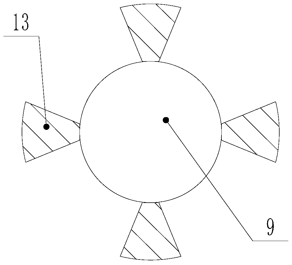
[0037] Such as figure 2 As shown, a power cable joint, the secondary clamping structure includes a torsion spring 11, a connecting plate 12 and a clamping plate 13, the connecting plate 12 is installed on the insulating layer 2 and the fastening layer 3, the connecting The plate 12 is connected with the clamping plate 13, and the two ends of the torsion spring 11 are respectively clamped on the connecting plate 12 and the clamping plate 13. Other parts are identical with embodiment 1.
[0038] The insulating layer 2 is connected to the bell jar flange 6 through screws; the bell jar flange 6 is provided with a sealing ring; the secondary clamping structure is provided with four to eight places, which are radially clamped on the outer circumference of the cable superior.
[0039] The working principle of this embodiment is similar to that of Embodiment 2, the difference is that after the first cable 9 is inserted into the first cable connector and connected to the conductive ...
PUM
 Abstract
Description
Claims
Application Information
 - R&D Engineer
- R&D Manager
- IP Professional
- Industry Leading Data Capabilities
- Powerful AI technology
- Patent DNA Extraction
Browse by: Latest US Patents, China's latest patents, Technical Efficacy Thesaurus, Application Domain, Technology Topic.
© 2024 PatSnap. All rights reserved.Legal|Privacy policy|Modern Slavery Act Transparency Statement|Sitemap


