Rotor sheath of external rotor permanent magnet motor

A technology of rotor sheath and permanent magnet motor, which is applied to magnetic circuits, electrical components, electromechanical devices, etc., can solve the problems of reducing the service life of the rotor, reducing the strength of the sheath structure, and unable to dissipate heat, and achieves the effect of accelerating wind speed and heat dissipation. Good and reliable results

Inactive Publication Date: 2019-08-06
HARBIN UNIV OF SCI & TECH
View PDF12 Cites 2 Cited by
  • Summary
  • Abstract
  • Description
  • Claims
  • Application Information

AI Technical Summary

Problems solved by technology

[0003] Most of the existing rotor sheaths are directly sleeved on the rotor. Since the rotor sheaths are mostly cylindrical and have a relatively simple structure, when in use, the heat generated by the rotor during rotation will not be dissipated, and it will easily cause permanent damage to the inside of the rotor. The magnet is overheated, the rotor is damaged, and the service life of the rotor is reduced; the existing improvement methods of the sheath mostly stay in the form of sheath segmentation, etc. After the sheath is segmented, it is difficult to install and operate, and the structural strength of the sheath will be greatly reduced

Method used


Image

  • Rotor sheath of external rotor permanent magnet motor
  • Rotor sheath of external rotor permanent magnet motor
  • Rotor sheath of external rotor permanent magnet motor

Examples


Embodiment

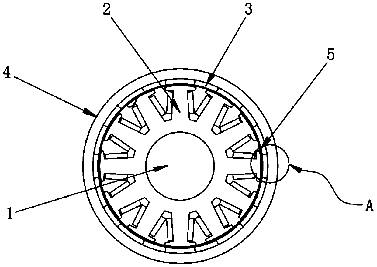
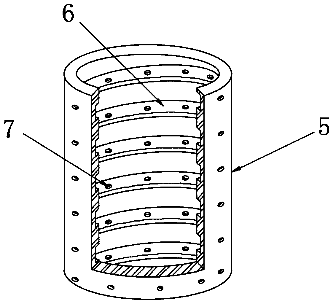
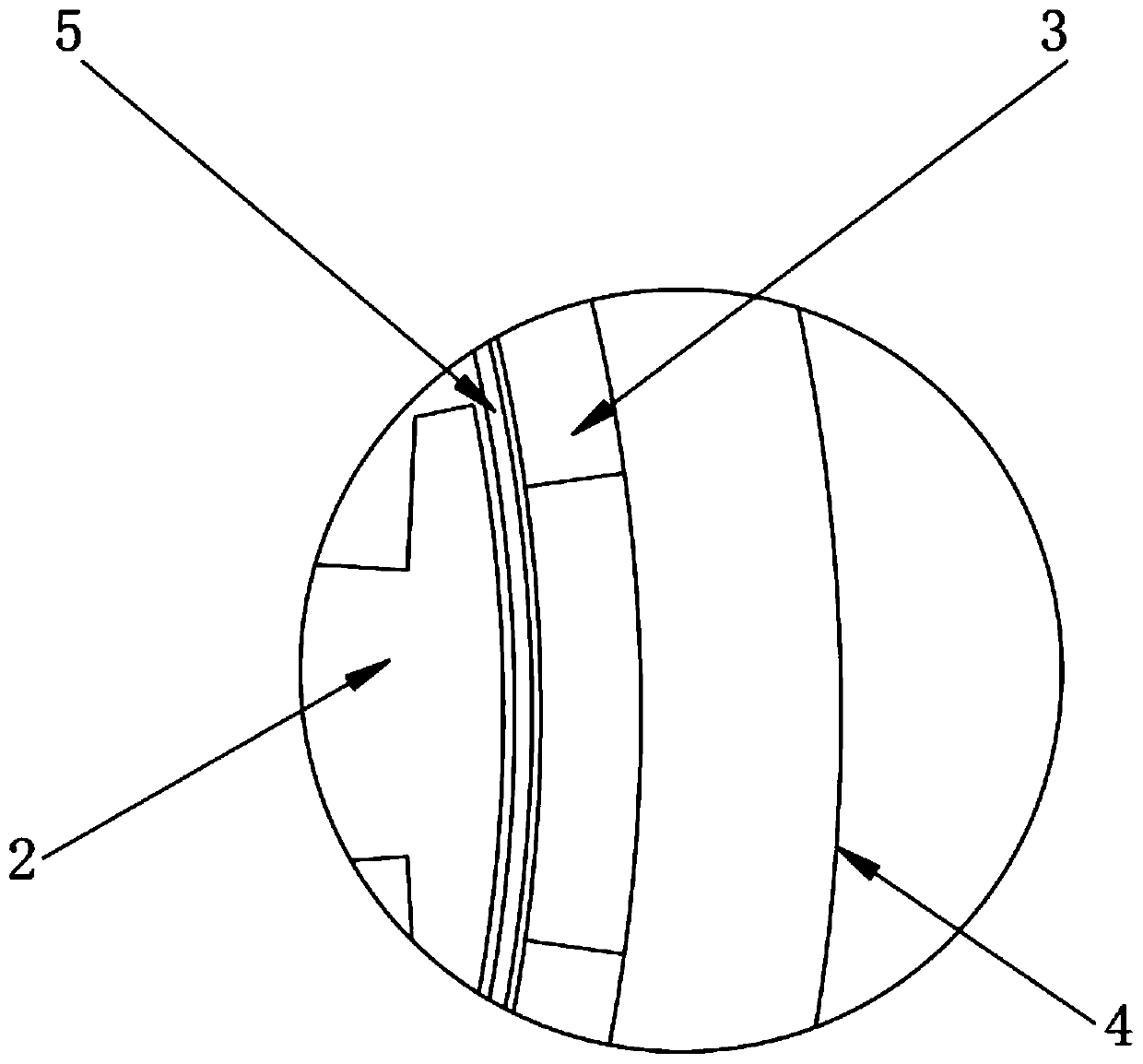
[0025] see Figure 1-3 , the present invention provides the following technical solutions: a rotor sheath of an outer rotor permanent magnet motor, including a rotating shaft 1, the outer wall of the rotating shaft 1 is provided with a stator 2, the rotating shaft 1 and the stator 2 are fixedly connected, and the stator 2 is provided with a rotor 4 on the outside, the rotor 4 is adapted to the stator 2, the inner wall of the rotor 4 is embedded with a permanent magnet 3, and a rotor sheath 5 is embedded in the interlayer between the permanent magnet 3 and the stator 2 , the inner wall of the rotor sheath 5 is provided with a spiral groove 6 from top to bottom, and the outer wall of the rotor sheath 5 is provided with a number of cooling slots 7, and the cooling slots 7 communicate with the spiral slot 6 .

[0026] In this embodiment, a spiral groove 6 is provided on the inner wall of the rotor sheath 5, and the helical groove 6 serves to accelerate the flow rate of the air ga...


PUM


Abstract

The invention belongs to the technical field of motor rotors, in particular to a rotor sheath of an external rotor permanent magnet motor. The motor comprises a rotating shaft and a stator which sleeves the outer wall of the rotating shaft. The rotating shaft and the stator are fixedly connected. A matching rotor is arranged on the outer side of the stator. Permanent magnets are embedded into theinner wall of the rotor. A rotor sheath is arranged in the interlayer between the permanent magnets and the stator. A spiral slot is arranged in the rotor sheath from top to bottom. Heat dissipation slots are arranged in the outer wall of the rotor sheath. The spiral slot is arranged in the rotor sheath to block the axial and circumferential eddy current paths of the sheath, so that the eddy current loss of the sheath is reduced. The spiral slot can increase the heat dissipation area of the rotor, speed up the wind in the air gap and improve the heat dissipation effect at the joint of the rotor and the rotor sheath. The processing technology of the spiral slot is less difficult, and the spiral slot can be made by simple turning. The heat dissipation slots are arranged in the outer wall ofthe rotor sheath to assist the spiral slot in heat dissipation, and thus, the heat dissipation effect is better.

Description

technical field [0001] The invention belongs to the technical field of motor rotors, and in particular relates to a rotor sheath of an outer rotor permanent magnet motor. Background technique [0002] The rotor of the motor is also the rotating part of the motor. The motor is composed of two parts: the rotor and the stator. It is used to realize the conversion device of electrical energy and mechanical energy and mechanical energy and electrical energy. There are two ways of rotor rotation and outer rotor rotation. The rotation mode of the inner rotor is that the core body in the middle of the motor is a rotating body, output torque (referring to the motor) or input energy (referring to the generator), and the rotation mode of the outer rotor is to use the outer body of the motor as the rotating body. Different methods are convenient for various occasions. Applications. [0003] Most of the existing rotor sheaths are directly sleeved on the rotor. Since the rotor sheaths a...

Claims


Application Information

Patent Timeline
Patent Type & Authority Applications(China)
IPC IPC(8): H02K1/27H02K1/32
CPCH02K1/2786H02K1/32
Inventor 梁艳萍钱炳杉
Owner HARBIN UNIV OF SCI & TECH
Why Eureka
Try Eureka