
Ultrasonic imaging space compounding method and system

A space composite, ultrasonic imaging technology, applied in radio wave measurement system, ultrasonic/sonic/infrasound equipment control, ultrasonic/sonic/infrasonic diagnosis, etc. , to achieve the effect of avoiding image sluggishness and avoiding smearing

Active Publication Date: 2019-08-09
VINNO TECH (SUZHOU) CO LTD
View PDF15 Cites 9 Cited by
  • Summary
  • Abstract
  • Description
  • Claims
  • Application Information

AI Technical Summary

Problems solved by technology

[0007] However, the existing technology can meet the real-time requirements, and the frame rate will not be reduced, but when the composite angle is large or there are many angles, the image will appear serious sluggishness and smearing, that is, the time resolution of the image will be reduced

Method used


Image

  • Ultrasonic imaging space compounding method and system
  • Ultrasonic imaging space compounding method and system
  • Ultrasonic imaging space compounding method and system

Examples


Embodiment Construction

[0048] The present invention will be described in detail below in conjunction with specific embodiments shown in the accompanying drawings. However, these embodiments do not limit the present invention, and any structural, method, or functional changes made by those skilled in the art according to these embodiments are included in the protection scope of the present invention.

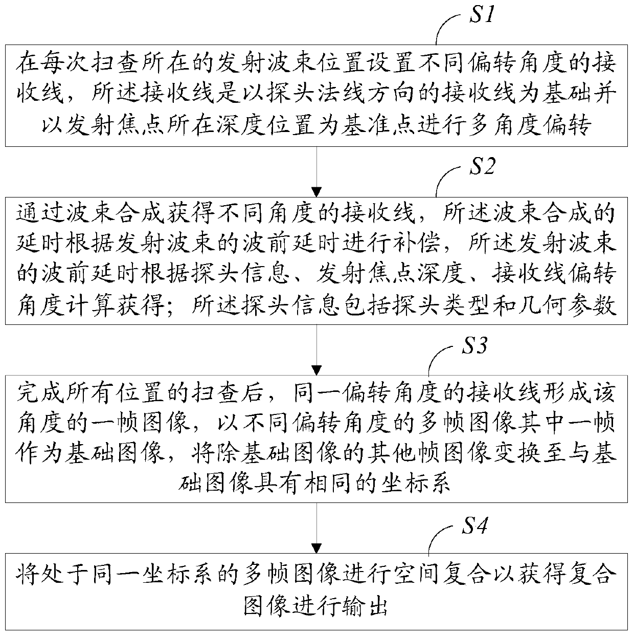
[0049] Such as figure 2 As shown, an embodiment of the present invention provides a method for spatial compounding of ultrasonic imaging, the method comprising:

[0050] S1. Set receiving lines with different deflection angles at the position of the transmitting beam for each scan. The receiving lines are based on the receiving line in the normal direction of the probe and take the depth position of the transmitting focus as the reference point for multi-angle deflection.

[0051] S2. Obtain receiving lines at different angles through beamforming, and the delay of the beamforming is compensated accor...


PUM


Abstract

The invention provides an ultrasonic imaging space compounding method and system. The method comprises the steps that receiving lines with different deflection angles are arranged at a transmitting beam position where each time of scanning is located, wherein the receiving lines are subjected to multi-angle deflection with the normal direction of a probe as the basis and the depth position of a transmitting focal point as a reference point; the receiving lines at different angles are obtained through beam synthesis, and the delay of beam synthesis is compensated according to the wavefront delay of the transmitting beams; after scanning of all positions is completed, the receiving lines at the same deflection angle form a frame of image at the angle, one of multiple frames of images with different deflection angles serves as a basic image, and other frames of images except the basic image are transformed to have a coordinate system same as that of the basic image; spatial compounding iscarried out on the multiple frames of images in the same coordinate system so as to obtain a composite image for outputting. According to the method and system, the time resolution of imaging is notinfluenced, and the phenomena of image dullness and trailing caused by the prior art are avoided.

Description

technical field [0001] The invention belongs to the field of medical ultrasonic diagnostic imaging, in particular to an ultrasonic imaging space composite method and system. Background technique [0002] Ultrasound imaging has become one of the most widely used clinical diagnostic tools because of its non-invasive, real-time, convenient operation, and low price. During the ultrasonic imaging process: the probe emits a focused ultrasonic beam, and each element of the probe receives the ultrasonic echo signal and enters each channel for amplification and filtering processing. The channel-level signal is subjected to beam synthesis to obtain a radio frequency signal (RF signal), and the above scanning process is repeated. Until a frame of radio frequency signal with a certain linear density is obtained, the radio frequency signal is processed by demodulation and filtering to obtain an orthogonal signal (IQ signal), the orthogonal signal is processed to obtain an image, and the ...

Claims


Application Information

Patent Timeline
Patent Type & Authority Applications(China)
IPC IPC(8): A61B8/00
CPCA61B8/5215A61B8/4444A61B8/5253A61B8/54A61B8/5207G01S15/8995G01S7/52085G01S15/8918G01S15/892
Inventor 凌涛马睿
Owner VINNO TECH (SUZHOU) CO LTD
Learn More