Movable clamping working table for round steel machining

A mobile and workbench technology, applied in the direction of metal processing equipment, metal processing machinery parts, clamping, etc., can solve the problems of inconvenient movement, slow clamping speed, difficulty in meeting people's daily processing needs, etc., to solve the problem of clamping speed Slow, fast clamping speed, the effect of improving work efficiency

Inactive Publication Date: 2019-08-09
蒋艳红
View PDF6 Cites 70 Cited by
  • Summary
  • Abstract
  • Description
  • Claims
  • Application Information

AI Technical Summary

Problems solved by technology

[0003] In the process of clamping round steel, the existing round steel clamping table has slow cl

Method used


Image

  • Movable clamping working table for round steel machining
  • Movable clamping working table for round steel machining
  • Movable clamping working table for round steel machining

Examples


Embodiment 1

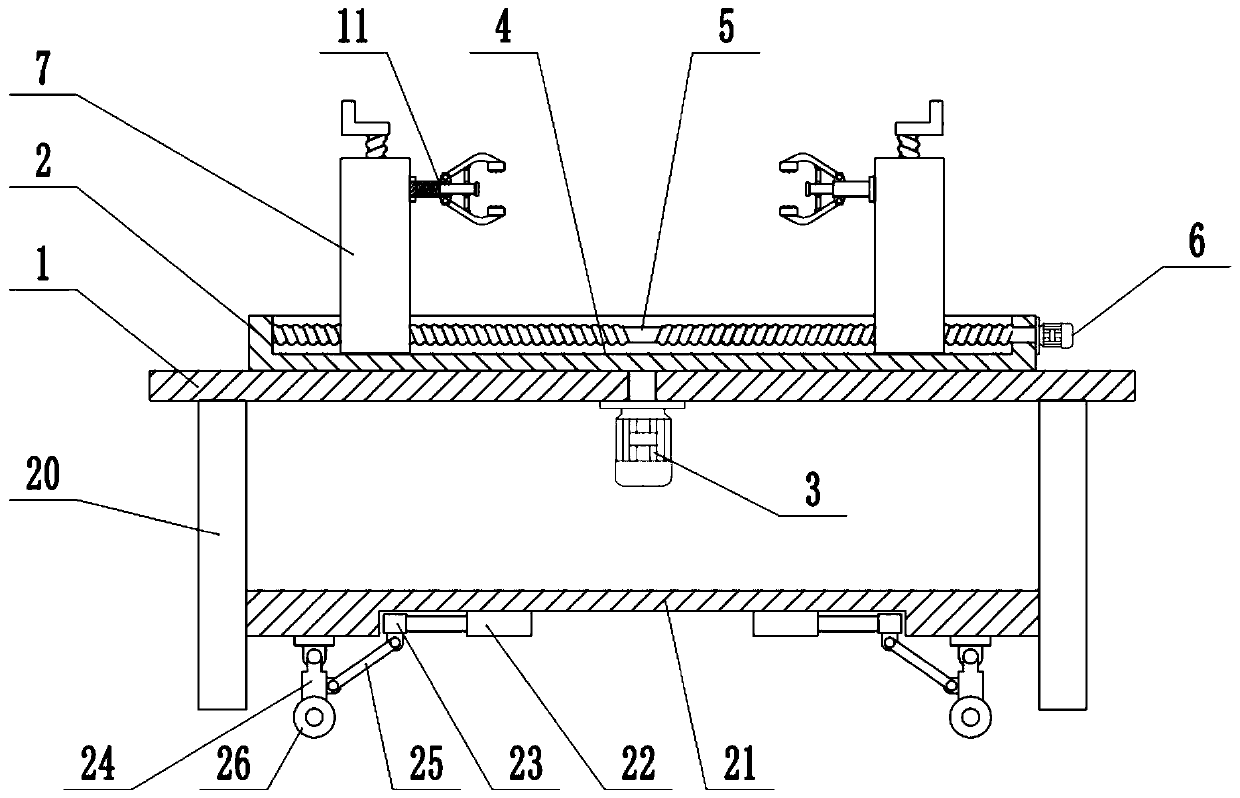
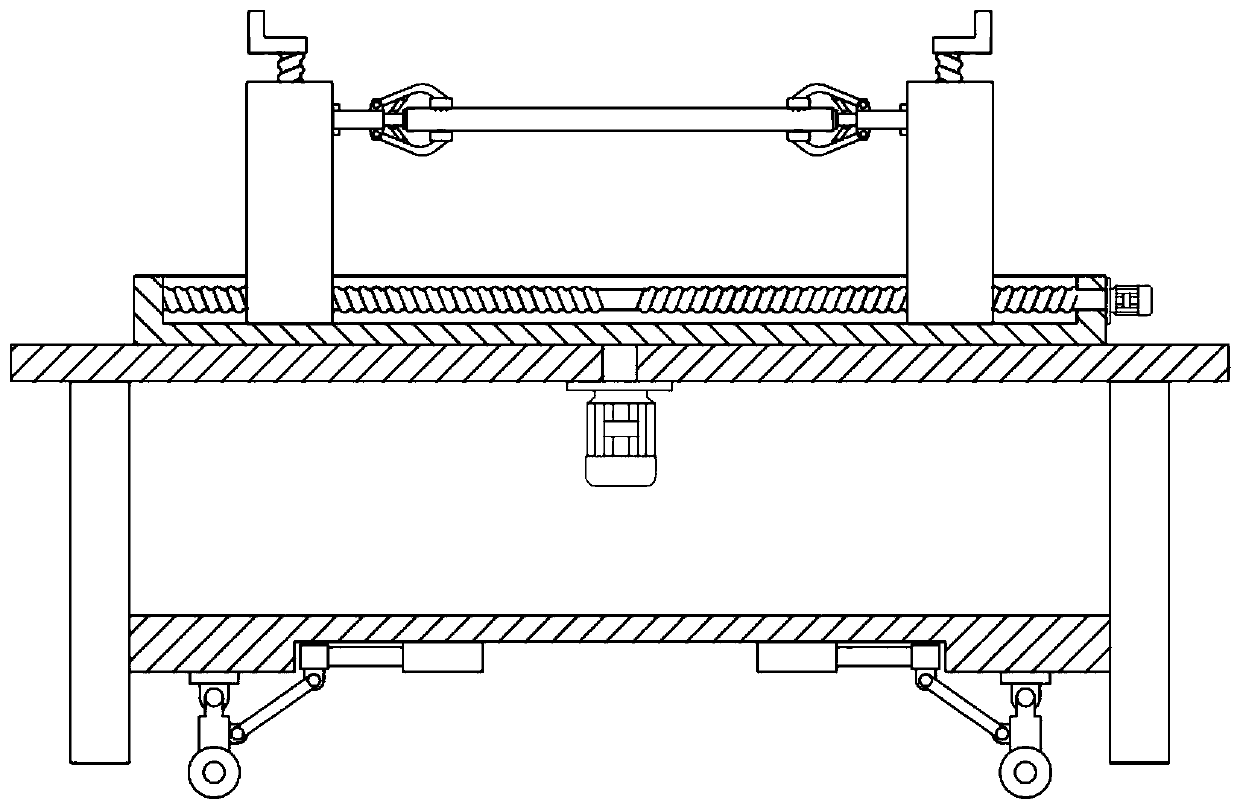
[0023] see Figure 1-5 , in an embodiment of the present invention, a mobile clamping workbench for round steel processing includes a table top 1, a rotary table 2, a two-way screw rod 5 and a movable support 7, and the upper surface of the table top 1 is rotatably connected with a rotary table 2 , the bottom of the table top 1 is fixedly connected with a rotary motor 3, and the shaft end of the rotary motor 3 passes through the table top 1 and is fixedly connected with the bottom of the rotary table 2, and the rotary motor 3 is started to drive the rotary table 2 to rotate, and the upper surface of the rotary table 2 A chute 4 is provided, and a two-way screw rod 5 is installed inside the chute 4, and the left and right ends of the two-way screw rod 5 are respectively connected to the side wall of the chute 4 in rotation, and the outer wall of the rotary table 2 is fixedly connected with a clamping motor 6 , the shaft extension end of the clamping motor 6 is fixedly connected...

Embodiment 2

[0027] On the basis of Embodiment 1, the bottom of the table top 1 is fixedly connected with a support plate 20. There are two support plates 20 arranged symmetrically on the left and right. Fixedly connected, the lower surface of the fixed plate 21 is equipped with a moving mechanism, the moving mechanism includes a telescopic mechanism 22, a slide block 23, a support rod 24, a movable rod 25 and a universal wheel 26, and the lower surface of the fixed plate 21 is fixedly connected with a telescopic mechanism 22 , the telescopic mechanism 22 is an electrohydraulic telescopic cylinder, the extended end of the telescopic mechanism 22 is fixedly connected with a slider 23, the slider 23 is slidably connected with the bottom of the fixed plate 21, the lower surface of the slider 23 is hinged with a movable rod 25, and the fixed plate The lower surface of 21 is hinged with support rod 24, and the lower end of support rod 24 is equipped with universal wheel 26, and the lower end of ...

Embodiment 1、 Embodiment 2

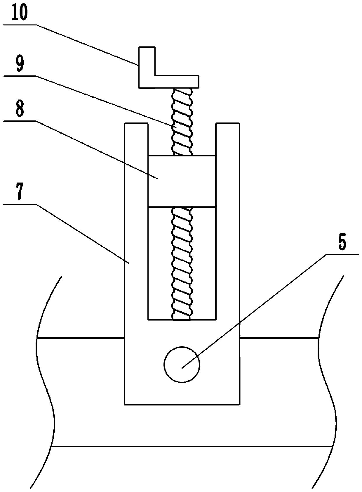
[0028] In conjunction with Embodiment 1 and Embodiment 2, the working principle of the present invention is: place the end of the round steel to be processed in the clamping mechanism 11, start the clamping motor 6, drive the two-way screw mandrel 5 to rotate, and then drive two The movable bracket 7 moves towards each other, so that the end of the round steel contacts the fixed block 15, pushes the slide bar 14 to move to the inside of the casing 12, and uses the connecting rod 16 to drive the jaws 13 to rotate, and the two jaws 13 are closed together. The clamping plate 17 clamps the end of the round steel to complete the clamping action. The clamping speed is fast, which greatly improves the work efficiency. When the rotating motor 3 is started, the rotary table 2 can be driven to rotate, thereby adjusting the position of the round steel, which is convenient for processing and turning. Shake the handle 10 to drive the lifting block 8 to move up and down. The height of the ro...


PUM


Abstract

The invention relates to the field of machining equipment, in particular to a movable clamping working table for round steel machining. The movable clamping working table comprises a table top, a rotating table, a two-way lead screw and a movable bracket, the upper surface of the table top is rotationally connected with the rotating table, a sliding groove is formed in the upper surface of the rotating table, the two-way lead screw is mounted inside the sliding groove, the outer side wall of the rotating table is fixedly connected with a clamping motor, the movable bracket sleeves the two-waylead screw, a guiding groove is longitudinally formed in the side wall of the movable bracket, a lifting lead screw is arranged in the guiding groove, a lifting block sleeves the lifting lead screw, and a clamping mechanism is mounted on the side wall of the lifting block. By arranging the two-way lead screw and the movable bracket, the end of round steel is clamped by a clamping plate to completeclamping action, the clamping speed is high, the working efficiency is greatly improved, by arranging the lifting block and the lifting lead screw, the height of the round steel can be adjusted according to the actual machining needs, and by arranging universal wheels capable of rising and falling, the movable clamping working table can be conveniently pushed to move.

Description

technical field [0001] The invention relates to the field of processing equipment, in particular to a movable clamping workbench for round steel processing. Background technique [0002] Round steel refers to a solid strip of steel with a circular cross section. Round steel is divided into three types: hot rolled, forged and cold drawn. The specifications of hot-rolled round steel are 5.5-250mm. Among them: 5.5-25 mm small round steel is mostly supplied in bundles of straight strips, which are often used as steel bars, bolts and various mechanical parts; round steel larger than 25 mm is mainly used for manufacturing mechanical parts and tube blanks of seamless steel pipes Wait. The shape of the round steel is smooth and round, without grain and ribs. Other steel bars have engraved lines or ribs on the surface. The round steel belongs to ordinary low-carbon steel, and most other steel bars are alloy steel. Other steel bars are strong. [0003] In the process of clamping ...

Claims


Application Information

Patent Timeline
IPC IPC(8): B23Q3/06B23Q1/25
CPCB23Q1/25B23Q3/064
Inventor 蒋艳红
Owner 蒋艳红
Why Eureka
Try Eureka