Cutter drive device

A driving device and cutting knife technology, applied in metal processing, household components, household appliances, etc., can solve the problems of slow cutting speed, unstable air flow, complex and bulky structure, etc., so as to reduce the impact and improve production efficiency. , the effect of reducing costs

Pending Publication Date: 2019-08-09
GUANGDONG LESHAN INTELLIGENT EQUIP CORP LTD
View PDF1 Cites 2 Cited by
  • Summary
  • Abstract
  • Description
  • Claims
  • Application Information

AI Technical Summary

Problems solved by technology

[0003] However, due to the complex and heavy structure of the above-mentioned structure, factors such as cylinder air pressure and air flow instability, the cutting speed of the cutter is slow and unstable, which affects the production efficiency.

Method used


Image

  • Cutter drive device
  • Cutter drive device
  • Cutter drive device

Examples


Embodiment 1

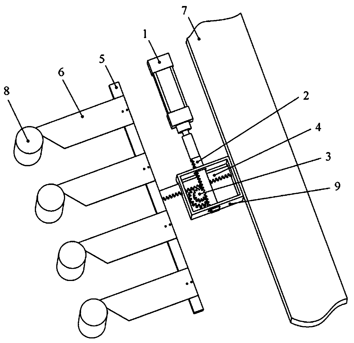
[0023] Such as figure 1 and figure 2 As shown, the present embodiment includes a cylinder 1, a cutter frame 5 and a cutter 6 installed on the cutter frame 5, a gear transmission mechanism is arranged between the cylinder 1 and the cutter frame 5, and the gear transmission mechanism includes a driving rack 2 , gear 3 and driven rack 4, gear 3 meshes with driving rack 2 and driven rack 4 respectively, driving rack 2 is coaxially connected with the telescopic rod of cylinder 1, and cylinder 1 drives driving rack 2 with the same To move, the driven rack 4 is arranged on the cutter frame 5.

[0024] The gear transmission mechanism is arranged on the frame beam 7, the frame beam 7 is provided with a gear box 9, the gear transmission mechanism is installed in the gear box 9, and the driving rack 2 and the driven rack 4 run through the gear box 9. Gear 3 is a double-circle gear composed of two large and small gears arranged coaxially. The driving rack 2 meshes with the pinion, and ...

Embodiment 2

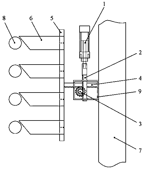
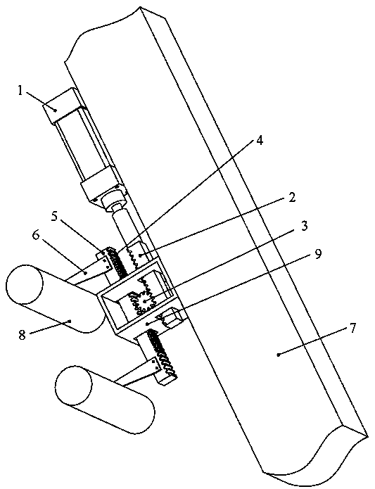
[0027] Such as image 3 and Figure 4 As shown, the present embodiment includes a cylinder 1, a cutter frame 5 and a cutter 6 installed on the cutter frame 5, a gear transmission mechanism is arranged between the cylinder 1 and the cutter frame 5, and the gear transmission mechanism includes a driving rack 2 , gear 3 and driven rack 4, gear 3 meshes with driving rack 2 and driven rack 4 respectively, driving rack 2 is coaxially connected with the telescopic rod of cylinder 1, and cylinder 1 drives driving rack 2 with the same To move, the driven rack 4 is arranged on the cutter frame 5.

[0028] The gear transmission mechanism is arranged on the frame beam 7, the frame beam 7 is provided with a gear box 9, the gear transmission mechanism is installed in the gear box 9, and the driving rack 2 and the driven rack 4 run through the gear box 9. The gear 3 is a single-turn gear, and the gear box 9 is provided with a driving rack through hole and a driven rack through hole, and th...


PUM


Abstract

The invention discloses a cutter drive device. The cutter drive device comprises an air cylinder (1), a cutter holder (5) and a cutter (6) installed on the cutter holder (5), wherein a gear transmission mechanism is arranged between the air cylinder (1) and the cutter holder (5), and comprises a driving rack (2), a gear (3) and a driven rack (4); the gear (3) is engaged with the driving rack (2) and the driven rack (4) separately; the driving rack (2) is coaxially connected with a telescopic rod of the air cylinder (1); and the driven rack (4) is arranged on the cutter holder (5). Through thecharacteristic that gear transmission can increase the speed, the opening and closing speed of the cutter is accelerated, the production efficiency is improved, and accordingly the influence of unstable factors of the air cylinder on the production efficiency is reduced.

Description

technical field [0001] The invention relates to a cutter driving device, which is suitable for a plastic bottle blowing machine. Background technique [0002] Existing plastic bottle blowing machines generally adopt air cylinders to directly drive the opening and closing of cutters to realize material cutting. For example, Chinese invention document CN201439207U discloses a cold cutter device, including a cutting blade, a blade pressing plate, a fixed seat, a fixing frame, a connecting plate, a cutter front plate, a cutter middle plate, a cutter rear plate and a driving mechanism, and the connecting plate is fixed. On the frame, the fixed frame is installed on the connecting plate, the fixed seat is fixed on the fixed frame, and the two cutting blades are respectively installed on the front plate of the cutter and the middle plate of the cutter through the blade pressure plate. The driving mechanism includes a cylinder, a second One rack, second rack and gear, the cylinder ...

Claims


Application Information

Patent Timeline
Patent Type & Authority Applications(China)
IPC IPC(8): B26D1/09B26D5/08B29C49/42
CPCB26D1/09B26D5/083B29C49/4252B29L2031/7158
Inventor 郭锡南黄斌斌郑俊峰
Owner GUANGDONG LESHAN INTELLIGENT EQUIP CORP LTD
Why Eureka
Try Eureka